If you think my subject line implies a blog post about some downtrodden Fiat owner whose Italian marvel needs ever-repetitive mechanical repair (an undeserved reputation which gave birth to the cliché that F.I.A.T. is an acronym “Fix It Again Tony”), you would be mistaken. Today’s story is about my friend Tony, a fellow member of the NJ Chapter of AROC (Alfa Romeo Owners Club) who asked me to assist him in getting his 1967 Alfa Giulia 1300 TI sedan started. It seems that while Tony did have the car out for a short spin around the block in early January, subsequent attempts at starting have proven futile. It took me a while to land on the right combination of a free afternoon and semi-decent winter weather, but that combination rang the bell on Sunday Feb. 25. Tony’s house is a quick 20-minute jaunt for me, so I threw a few tools into a small toolbox and headed his way.
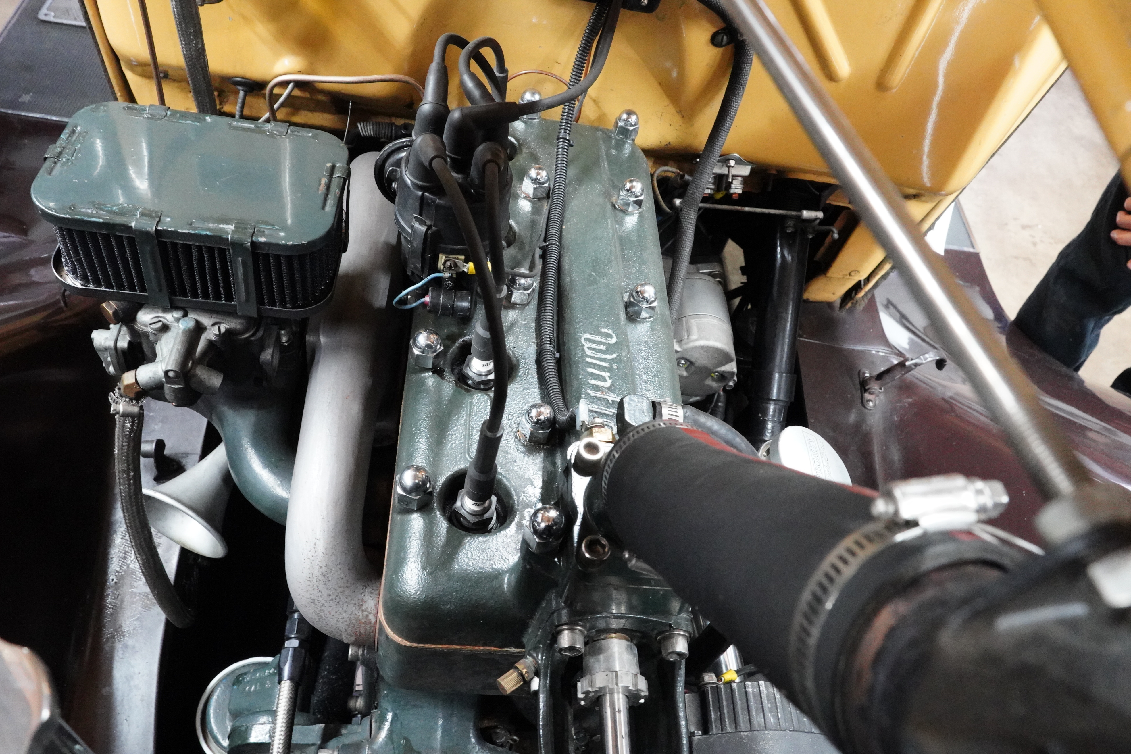
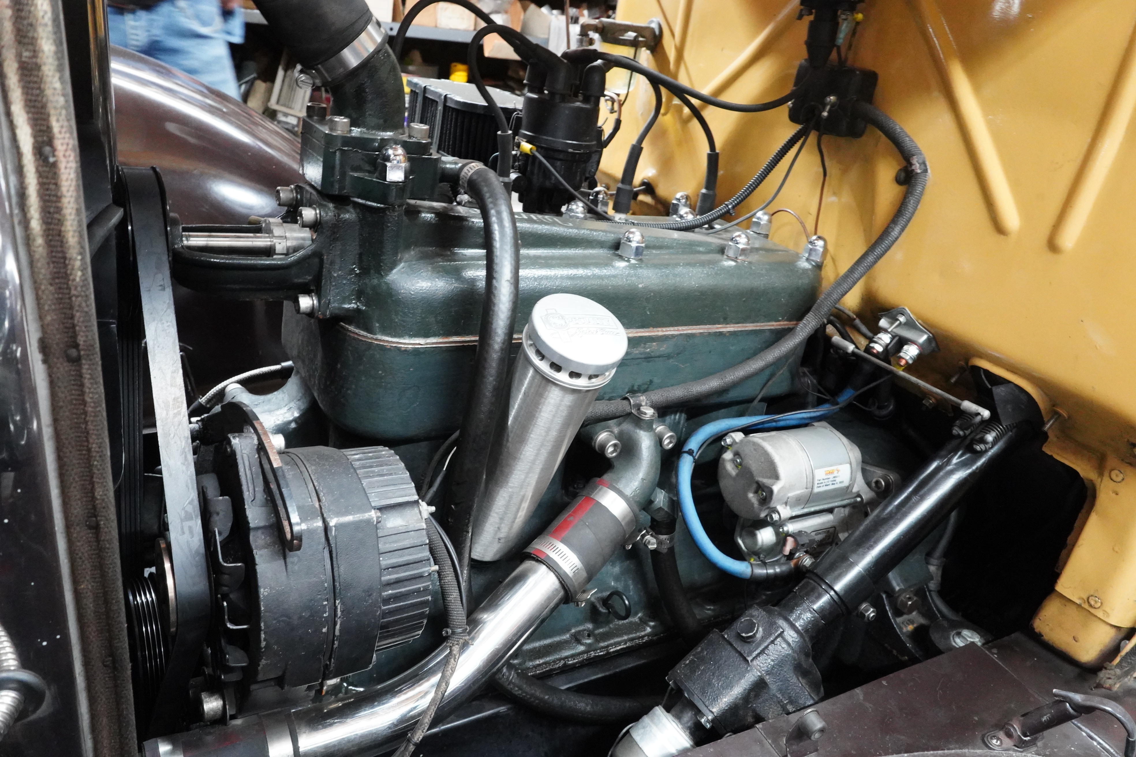
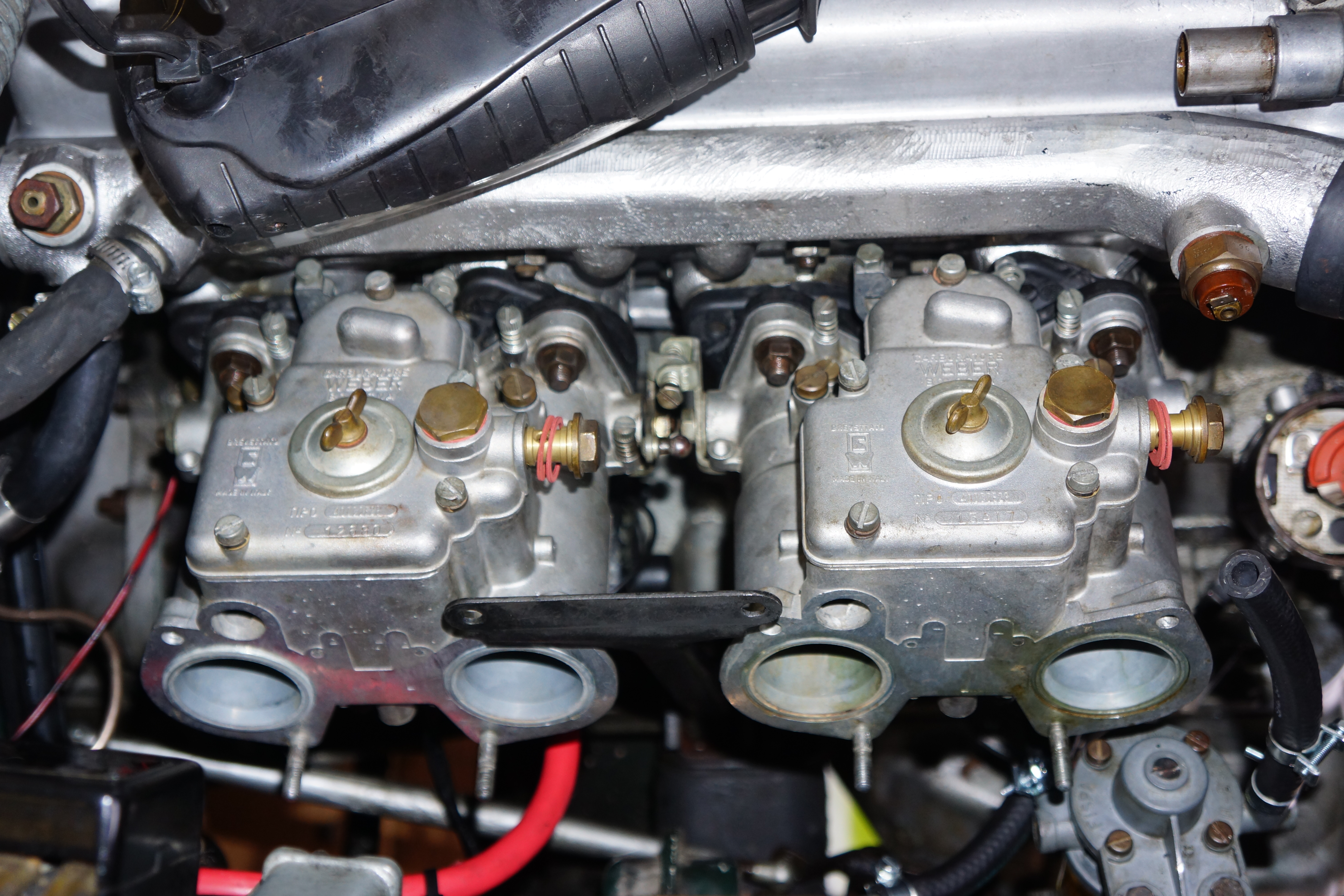
Like many older Alfas, Tony’s car is no longer 100% original. A while back, under his ownership, he had a shop swap out the factory 1.3L engine for a 2-liter job. If that engine was yanked from a U.S. spec car, the fuel system would have been Alfa’s unique Spica mechanical fuel injection. However, Tony’s engine wears a pair of the familiar Weber 40DCOE carbs, basically similar to what is on my GT Junior. Good thing, because I have not applied a wrench to anything Spica-related since 1980 (44 years for those of you who had a glass of vino rosso before opening my blog).
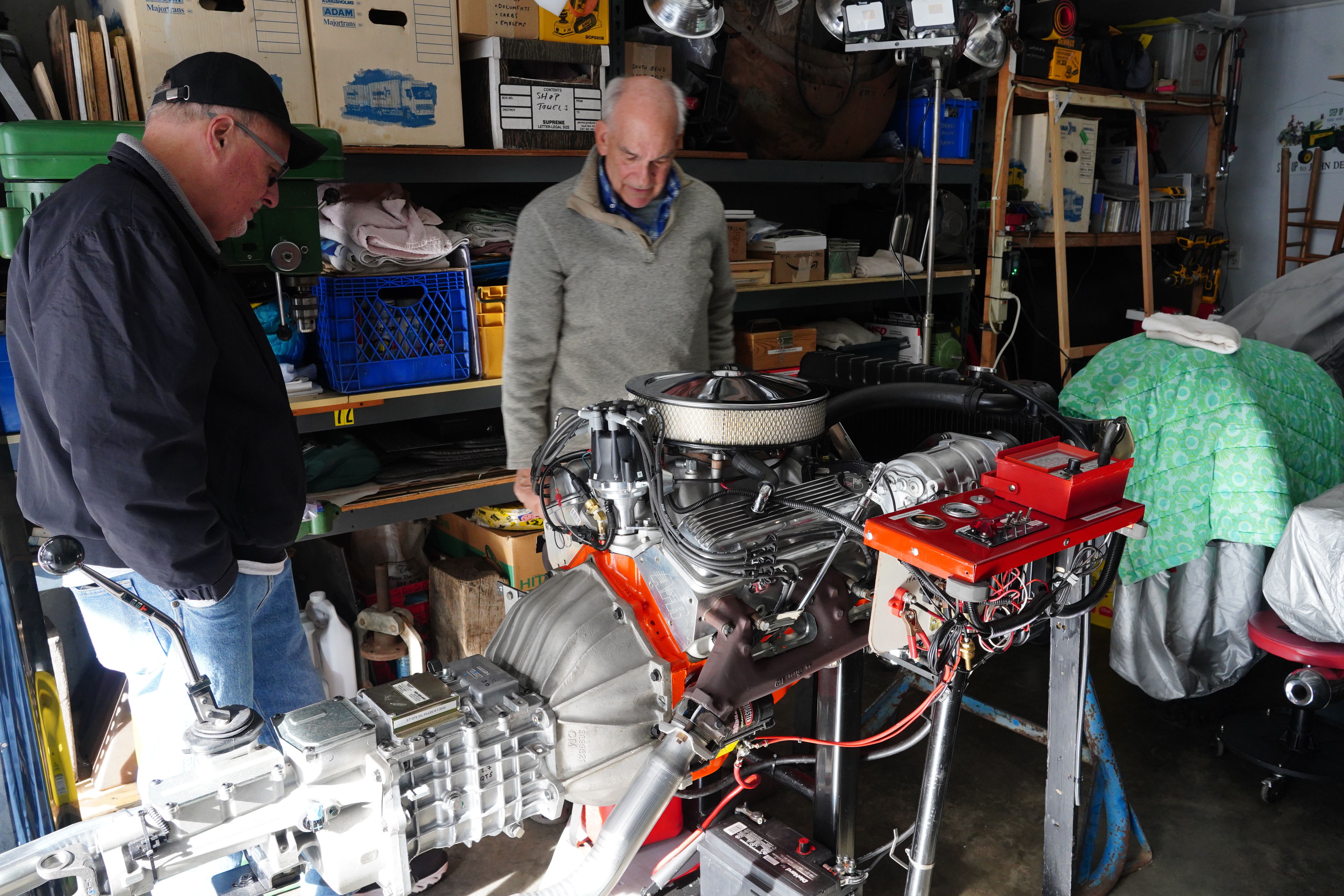
When I got to Tony’s house, I started by performing a quick visual check under the hood. Tony kept saying that he thought that the engine was not getting fuel. That well may have been so, but we still needed to start with the basics. He showed me an aftermarket (Bosch) electric fuel pump mounted on the right inner fender. The wiring and hoses associated with that pump looked ok. I then popped off the distributor cap, and because it was a bit dusty under there, wiped it with a clean cloth. The cap and rotor looked fine, and again, a modification was in place: instead of points and condenser, the ignition system used aftermarket electronics to collapse the primary circuit and energize the coil. There wasn’t too much I could do to verify that at this moment.
Initial underhood checks completed, I asked Tony to try to start the engine. The battery was strong enough to provide good cranking power, but after 3 attempts, each lasting about 10 seconds, the engine didn’t even cough. Tony told me that usually, the engine “tries” to start on the first or second crank attempt. I suggested that to check for fuel delivery, we could pull a hose and watch for fuel flow, but a simpler and safer method might be to pull a plug and smell it. With that, the #1 plug was removed, and the fuel smell was strong enough to convince me that fuel was making it that far. However, the plug was completely black from carbon, almost to the point of closing the gap. Using a nylon brush, I cleaned that plug, then did numbers 2, 3, and 4, returning each plug to its original home. “Try it again” I instructed, and he did. This time, the engine sound changed: on the 2nd and 3rd crank attempts, the engine sputtered and almost started. Tony quickly exclaimed ‘THAT’S what it normally does”. I point-blank told him: “you need spark plugs”. He didn’t have any spares, so into his Honda we jumped, and headed for the local Auto Zone.
The Auto Zone counter guy could not have been more helpful. We gave him part numbers for NGK, Champion, and Bosch spark plugs (we were prepared!) but he had none in stock. Back to the car, and off to an Advance Auto Parts store in the opposite direction. I told Tony that the primo choice would be the NGKs, and bingo, AAP had the NGKs on the counter pronto.
Twenty-five bucks lighter, Tony had us back to his house in a flash. Out for the second time came the old plugs, and in went the new NGKs. (NGK plugs from my experience never need gapping, and these plugs were no exception, although I still checked them). Fingers crossed, Tony hopped in, and the engine started on the second try. Good thing I guessed right!
We took it for a short spin around the neighborhood, me riding shotgun. The car ran a little rough, possibly from dirty fuel or a carb imbalance, but on the whole, Tony was pleased. On my way out, I told Tony that I think these engines eat plugs for breakfast, so no matter how many or how few miles I put on my Alfa, I change mine once a year. He said he would start doing the same.

The new NGKs about to be unboxed and threaded into place

With new plugs in place, Tony gets behind the wheel for another starting attempt

Fantastico! With engine idling, Tony gives it two thumbs up

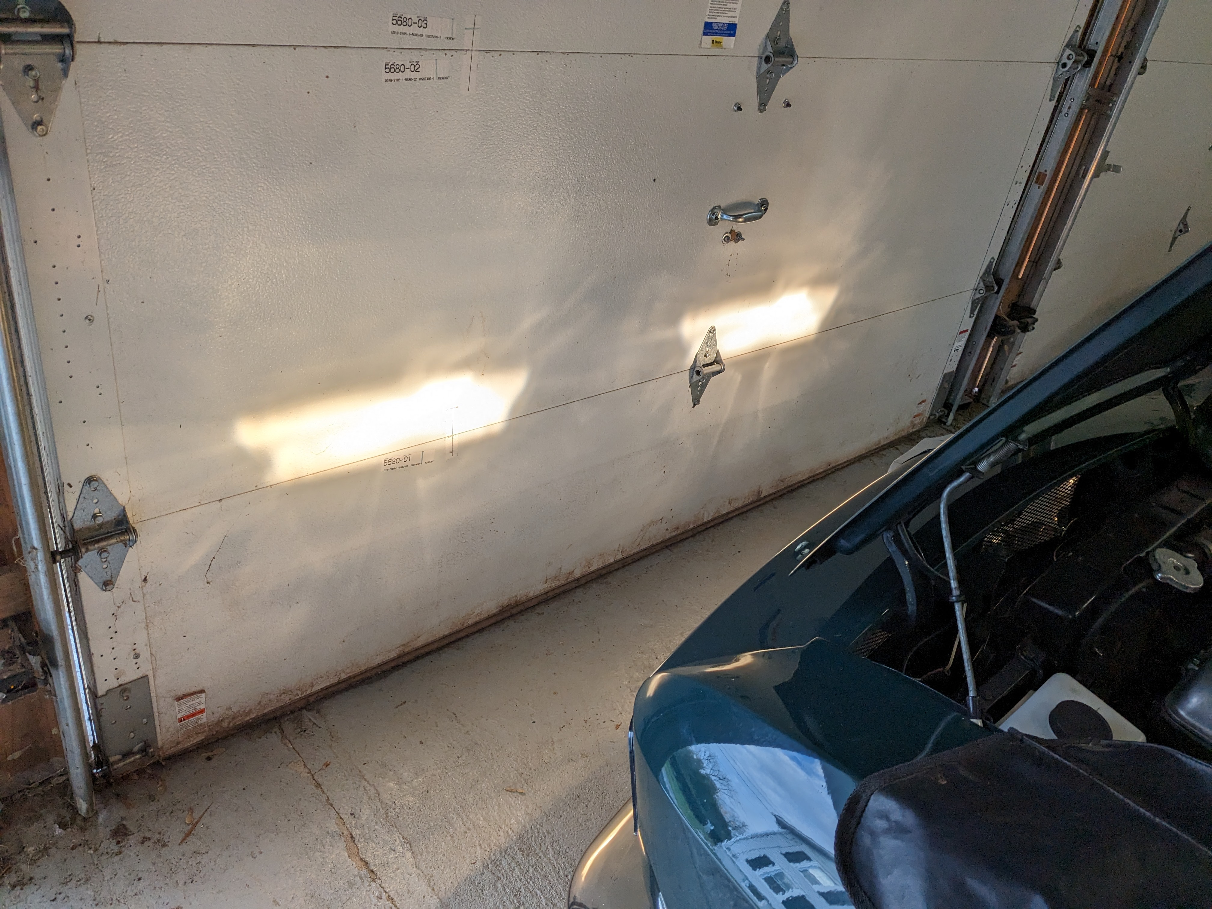
The uncatalyzed exhaust was quickly filling the garage, so Tony opened the door

Giulia TI (Tourist International) dash is completely different than my Bertone GT, and this one is a work of art in its own right

I tried it on for size; nice car!

Flying along on Route 22 at 50+ MPH (but the speedo reads in KPH, so more arithmetic)
All photographs copyright © 2024 Richard A. Reina. Photos may not be copied or reproduced without express written permission.