The Isetta Saga, Chapter 9: Overhauling the Car’s Compact Drivetrain

In Chapter 8, the front half of the chassis got back on its feet, er, wheels, while patiently waiting for some engine machine work to be completed. In Chapter 9 below, we make serious progress on one engine, while also making serious progress on the gearbox and rear axle.

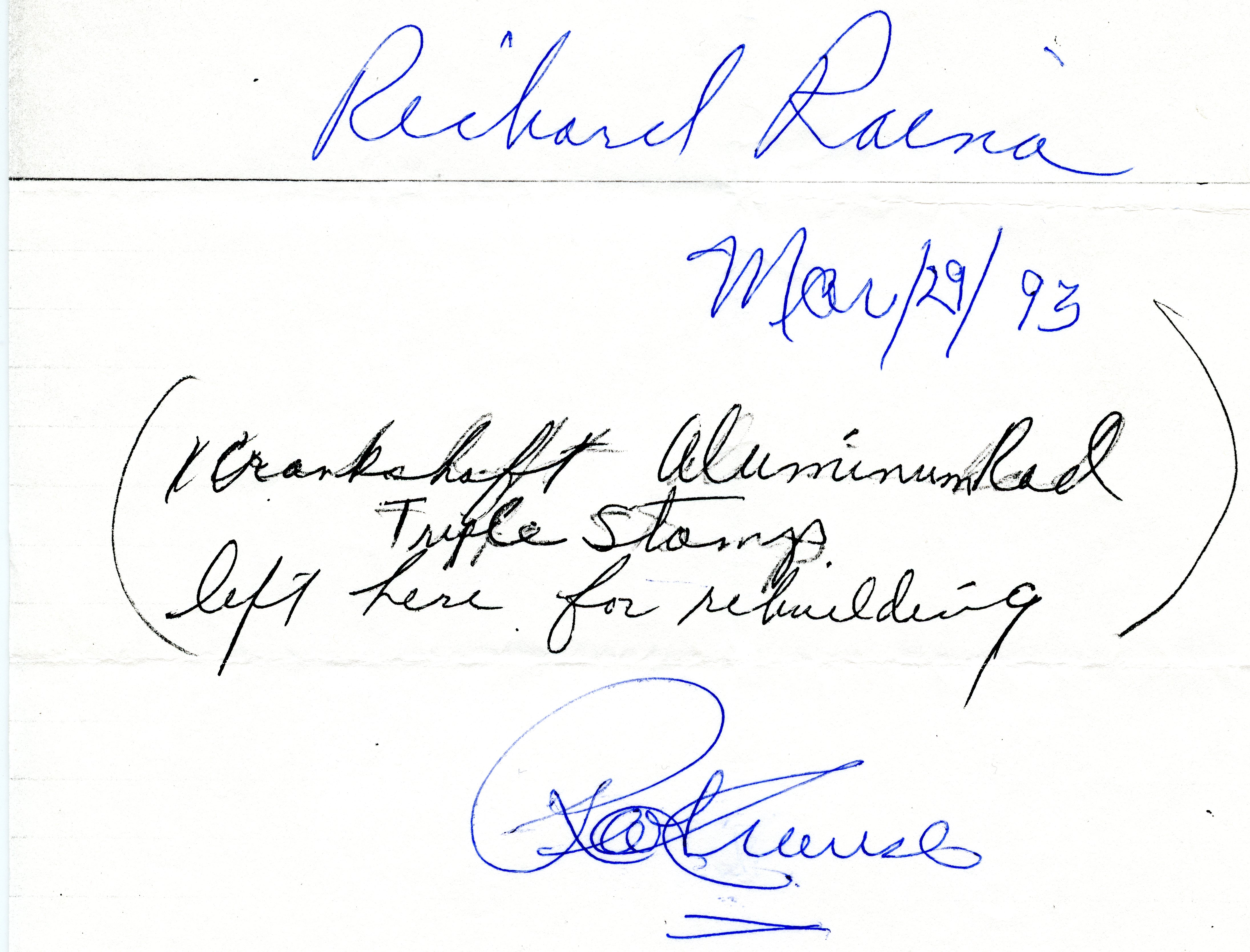
We last visited our engine progress in Chapter 7, which concluded with me leaving one crankshaft / connecting rod assembly in the hopefully-capable hands of Isetta restorer Ron Krause in PA. Ron said that he would take “a few weeks” to rebuild my crankshaft. I wasn’t exactly sitting around waiting for the phone to ring; I resumed work on the chassis, and as we saw in Chapter 8, got it up onto its two front tires again.

Sure enough, after a few weeks, Ron Krause called. My rebuilt crank/conrod was ready. I asked him if I could drop off a second one. He said he wasn’t one to turn down business. I drove to Emmaus once more, to pick up one assembly, and drop off another. I was becoming a regular. After a few days, Ron got back to me, stating that there was a problem. It seemed that BMW used both aluminum and steel connecting rods. The aluminum rods were notoriously weak. My second assembly used an aluminum rod, and it wasn’t rebuildable. Ron said that he could offer me an exchange unit for the same price. It wouldn’t be original to my car, but for such an internal part, it didn’t matter. I told him that I would go that route. He said he would have it ready for me in a few weeks.

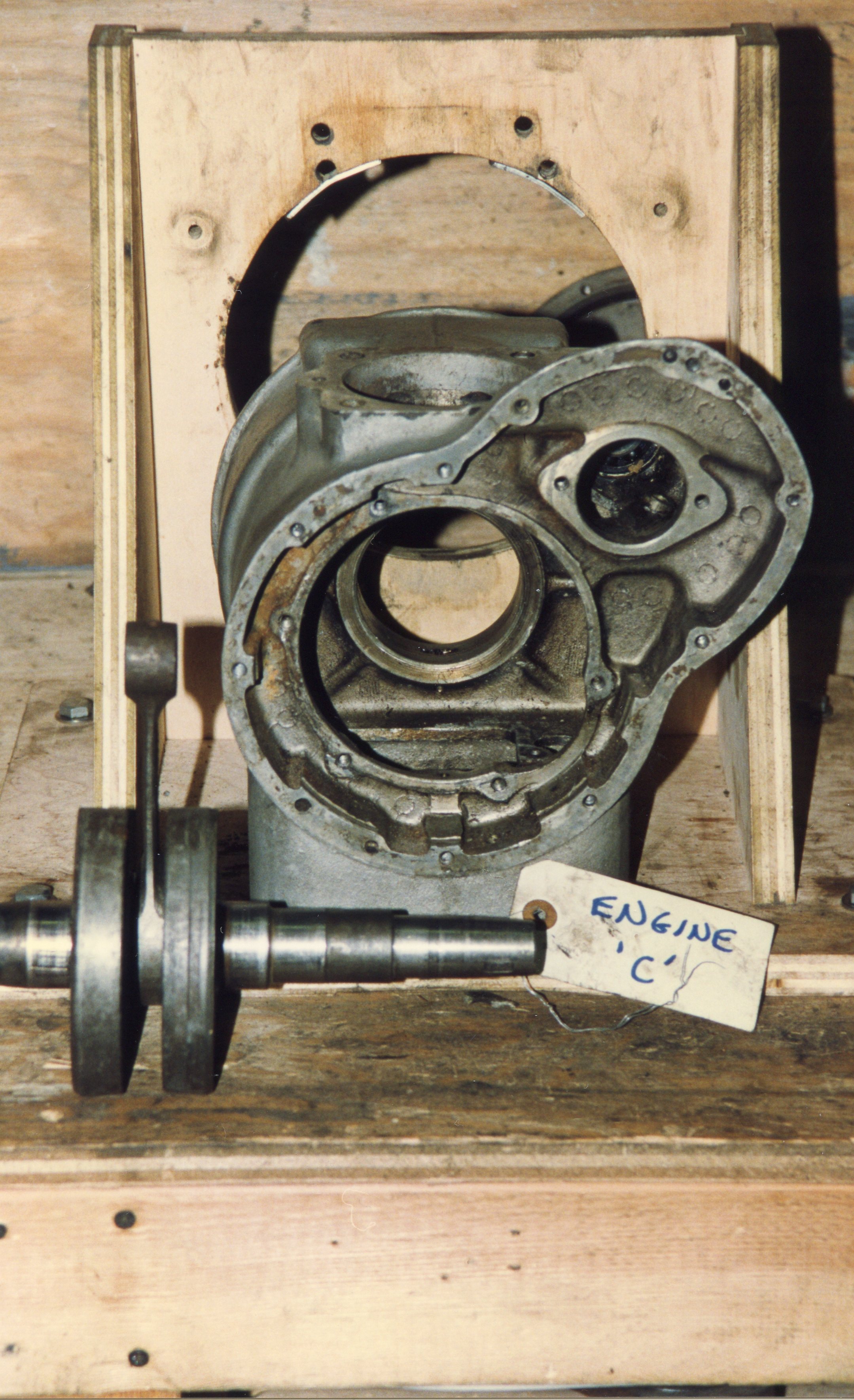
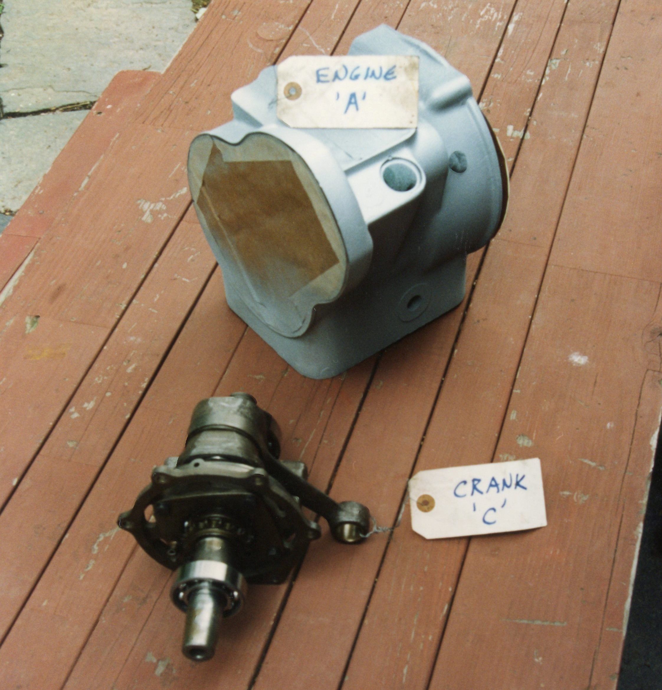
With one rebuilt crankshaft in hand, I could begin reassembly of an engine. Of course, as the repair guides love to state, “installation is the reverse of removal”, so the crankcase needed to be cooked again. But first, the bare case was cleaned as best as possible using solvents, was given an abrasive cleaning with a wire wheel in an electric drill, and was then painted with high-temperature aluminum paint out of a rattle can (as the store-bought spray paints are derisively called). In today’s world of high-end, no-expense-spared restorations, this kind of approach would be looked at as amateurish at best, and below-standard at worst. However, this was what I could afford while still keeping to a DIY standard. My Isetta was SUPPOSED to be a hobbyist restoration.

Engine case was cleaned using simple wire brush chucked into drill

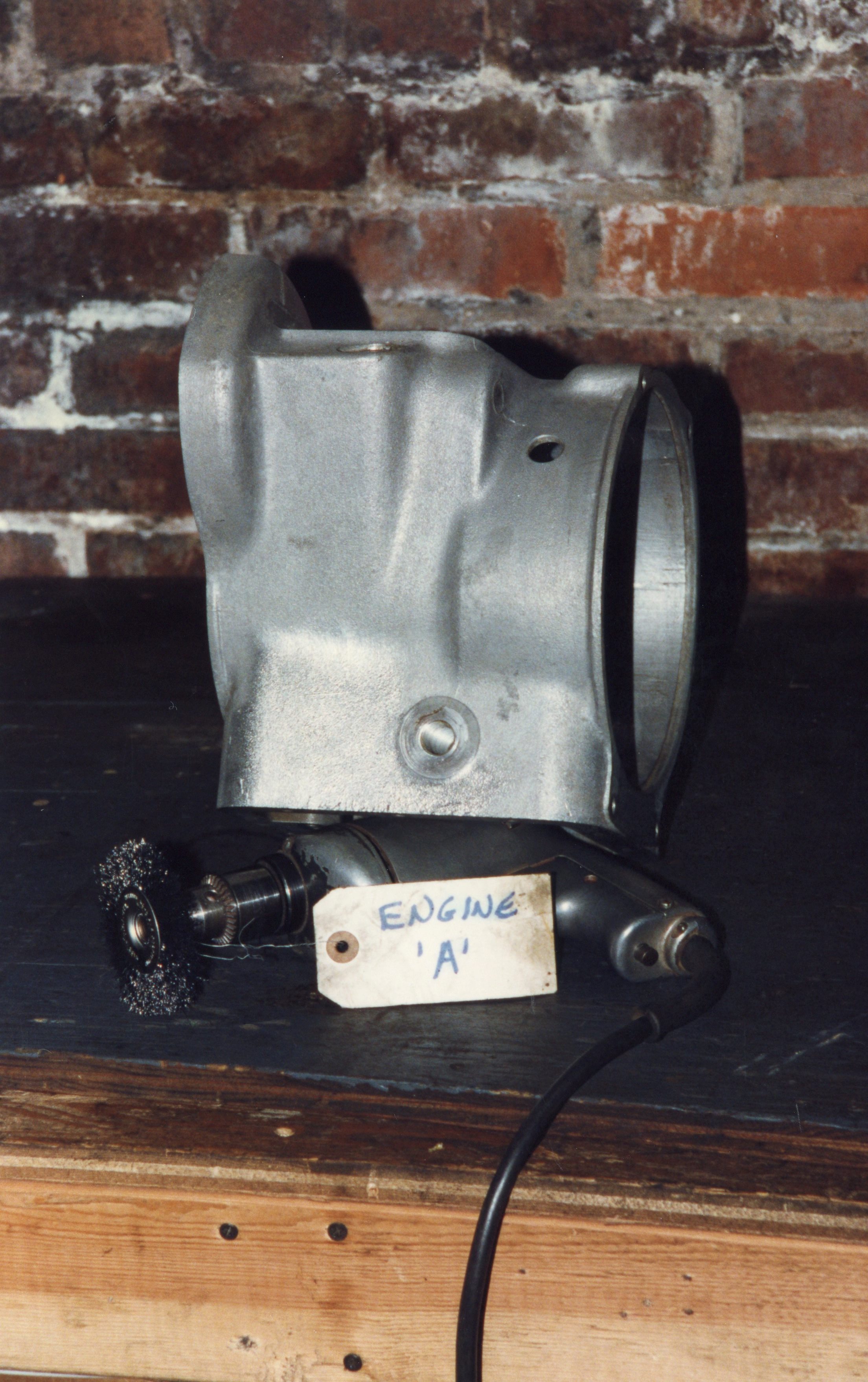
Allowing the paint to dry, I waited for an evening when my wife was not home, and turned on the kitchen oven to 400F. I put the crankcase in the oven and waited for 20 minutes. Oven mitts at the ready, I pulled out the superhot case, ran downstairs, picked up the crank/conrod assembly, and reinserted it. It went in like the book said it would. It was one of those moments in the journey where the progress felt profound.

Case is painted, crank ready to go back in

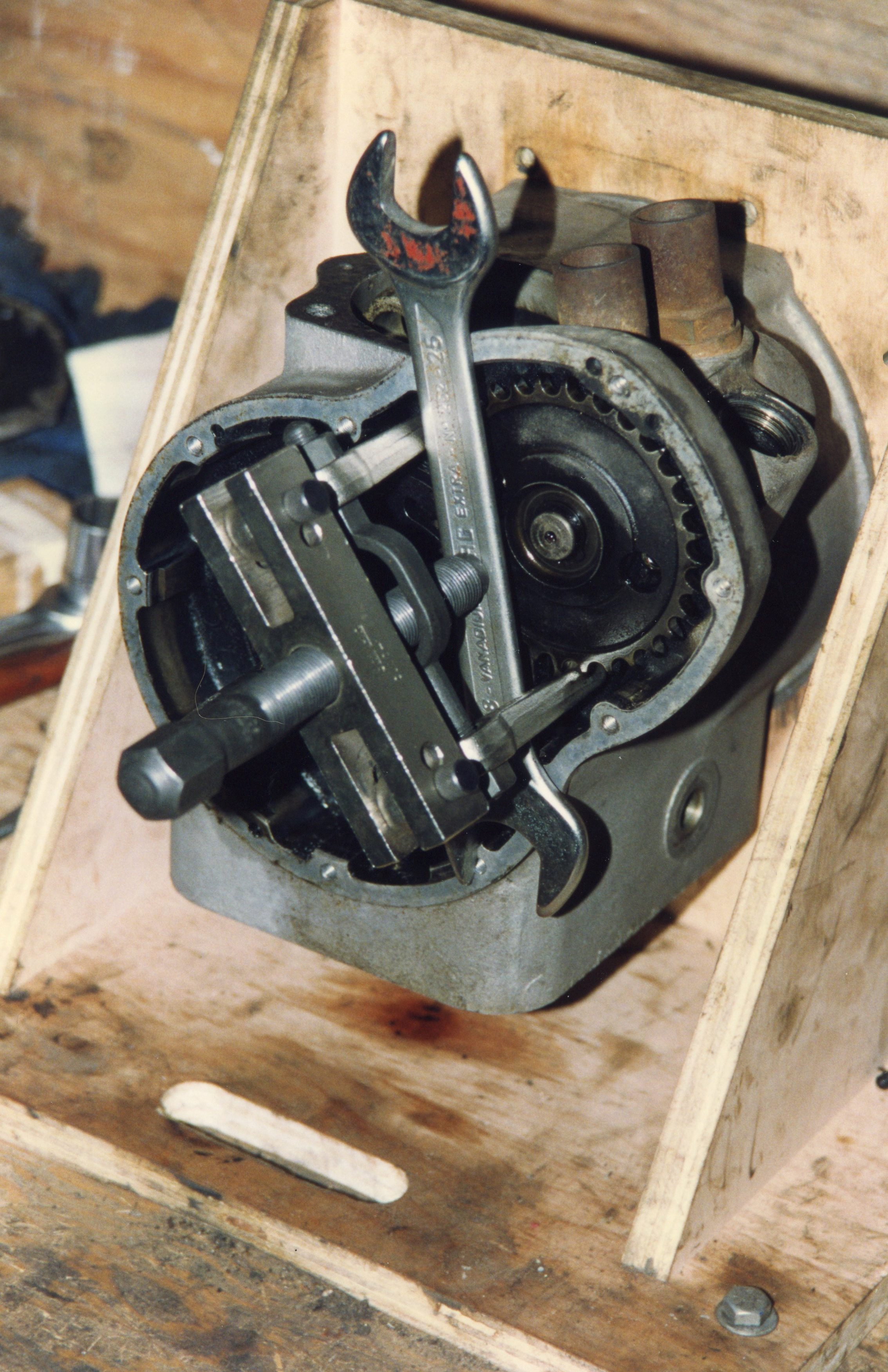
With the crankshaft back in place, the front of the engine could be reassembled. New timing chain, tensioner, and bearings were fitted. The camshaft was reinstalled, and new seals were used on the front of both crank and cam. The oil pump was reinstalled, and the oil pan was bolted in place, but not before hand-cutting an extra-thick cork gasket. John Jensen pointed out that when full, the engine oil is at a level ABOVE the oil pan gasket. I did not want this thing to leak if I could help it, so the cork gasket got silicone sealer on both sides, making for a nice sandwich between the crankcase and oil pan.


Two cylinder barrels, one unpainted, one cleaned and paintted


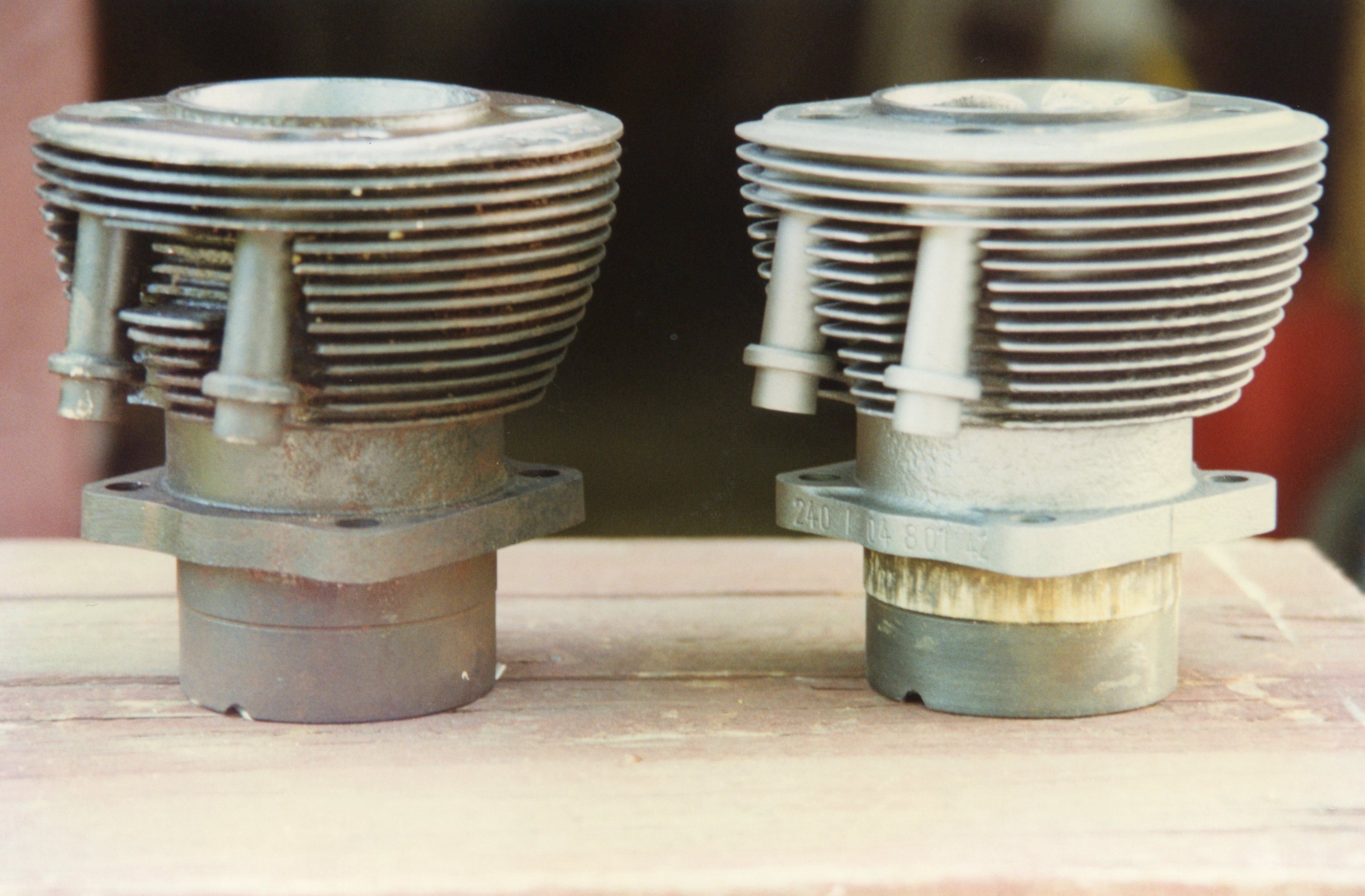
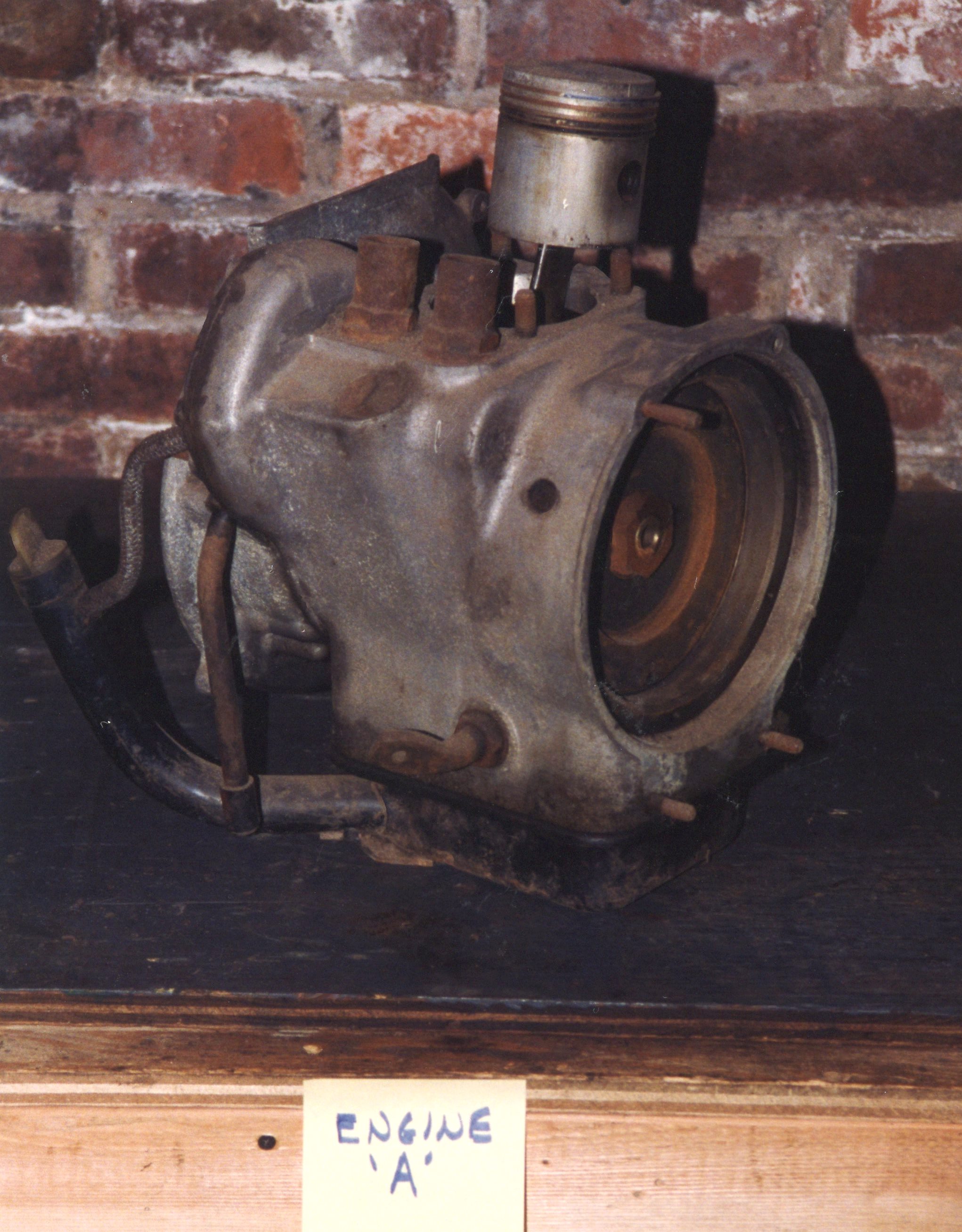
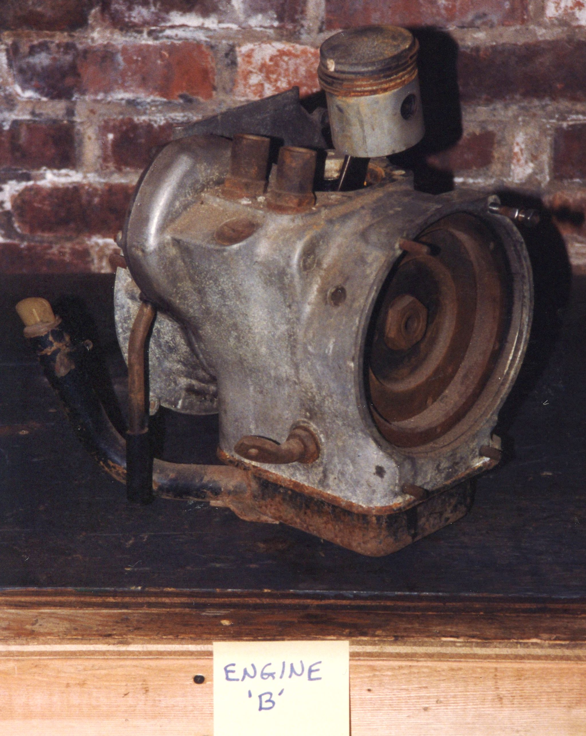
The cylinder barrels, surprisingly, did not show signs of broken fins. The two barrels were measured and were not out of spec. I bought a “small engine hone”, one designed for lawn mowers, and gave each barrel a light honing. These were cast iron and were painted with the appropriate paint. Pistons were reused (again, after measurements determined they were OK), and were fitted with new rings. Next in line: the cylinder head(s). I needed a good machine shop for that.

Lower end is essentially back together

While waiting for crank #2, and while researching machine shops, I grabbed the next part in line: the four-speed manual transmission. Of course, I had two, and from the outside, they looked identical. I chose one and ran with it. The other would be saved for my step-son. The transmission could be mounted to the same wooden engine stand as was used for the engine, once a few extra mounting holes were drilled (into the stand, not the tranny).

Two transmissions, identical except one on right has driveshaft attached (top)

(It has long been folklore in Isetta circles that their transmissions lack a reverse gear. I believe this bit of “fake news” came about because of the drivetrain’s motorcycle origins. However this falsehood began, it is simply not true. All Isetta manual transmissions were four-speed, fully synchronized on all forward speeds, with a reverse gear. A very, very, small number of Isettas were equipped with the Saxomat semi-automatic transmission.)

With cover off, it was a relief to see no broken gears; note roller bearings and shims


Transmission mounted to same wooden stand as used for engines

I had never rebuilt any kind of transmission before, manual or automatic. As a tech, I had replaced clutches and shifter mechanisms, and had serviced valve bodies, so it wasn’t something I feared. Here again, the John Jensen Isetta Restoration book was the go-to publication. The tranny, like much of the drivetrain, relied on roller bearings. Provided that no gears were broken, a rebuild consisted of replacing the bearings, seals and gaskets.

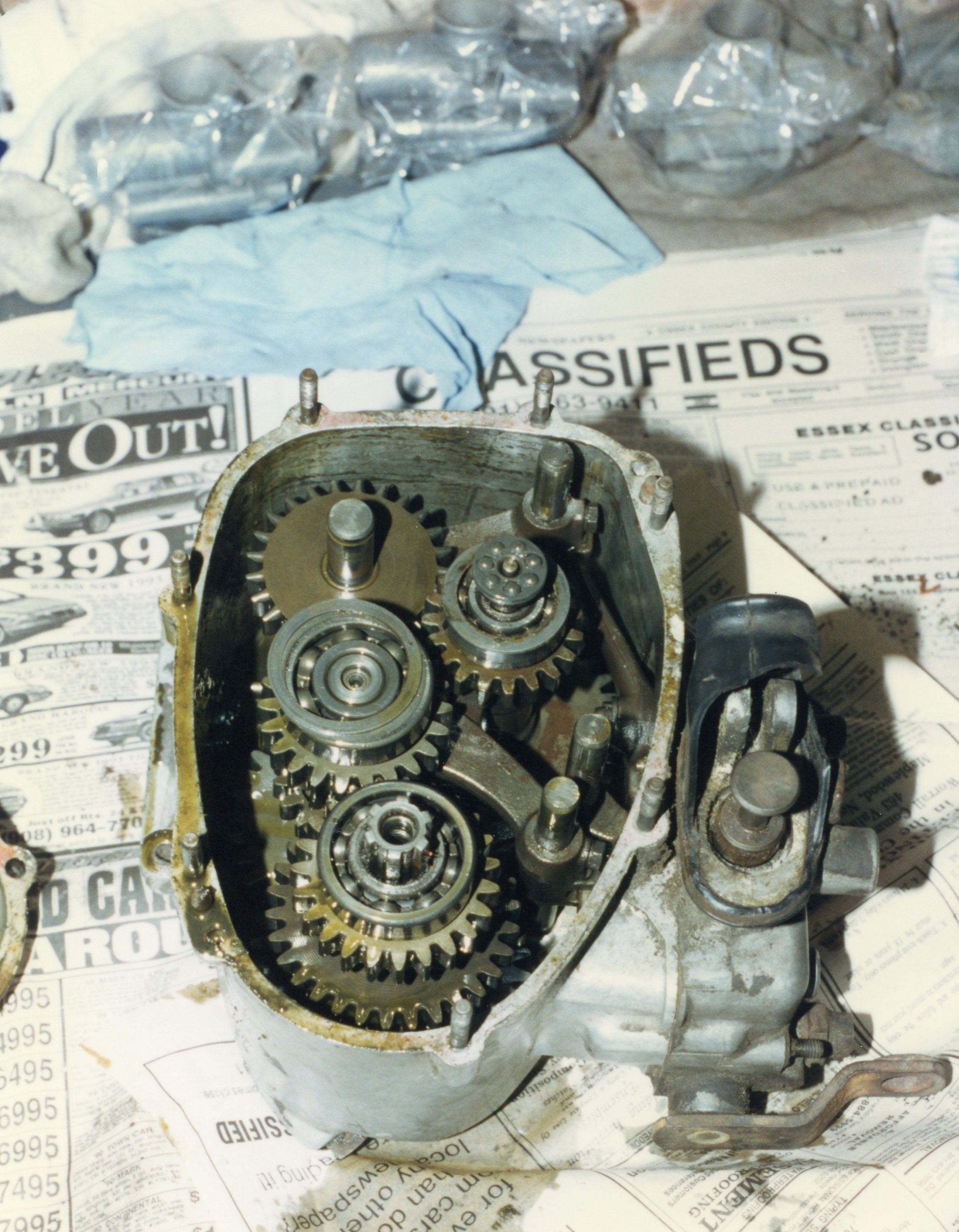
Once the front cover was off, the contrast with the innards compared to the engines’ was striking. Of course, transmissions do not normally circulate combustion by-products among their moving parts. The initial inspection showed clean and intact gears riding in rather clean oil.

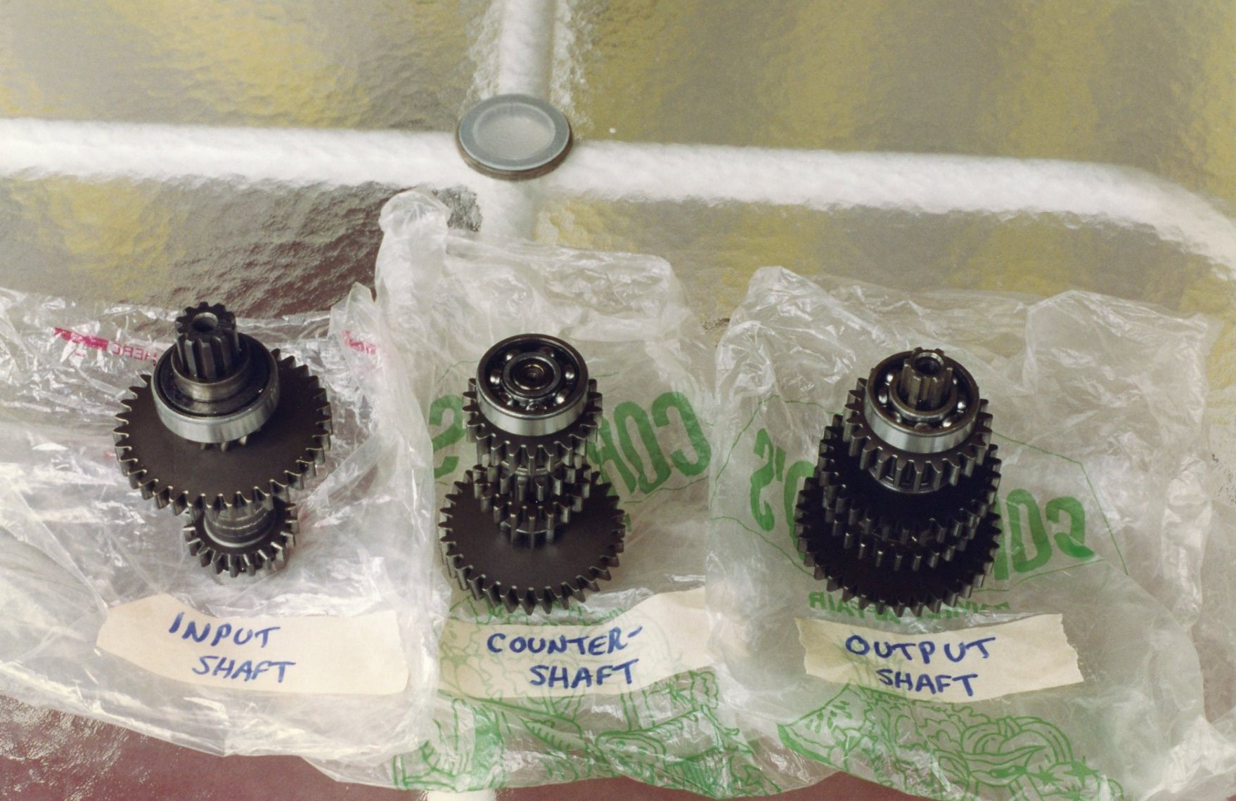
This gearbox was conventional in using three shafts: input, counter, and output. Each shaft was labeled as it was removed (they looked awfully similar outside the case). Roller bearings were standard metric sizes. The Jensen book provided the dimensions, and I was able to procure SKF bearings locally. (More about SKF and its connection to a certain Swedish car company is below under ‘FUN FACT OF THE WEEK’.)

Transmission case and covers, ready for paint

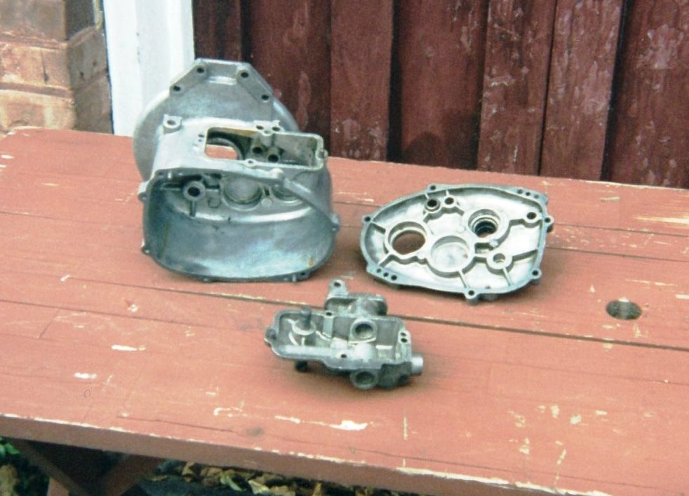
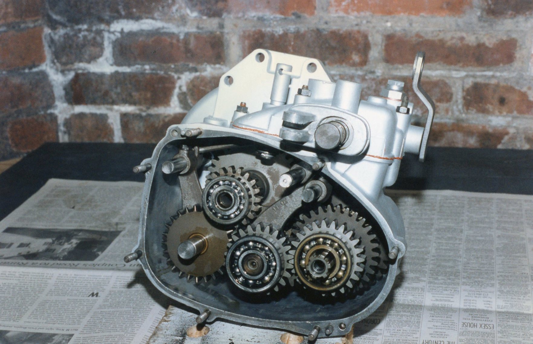
As was done with the crankcase, the transmission case and cover were cleaned, abraded, and painted. The three shafts were reinstalled into the freshly painted case.  I made my own gaskets for the covers, and all seams that needed to seal against oil were slathered with copper goop. Jensen warned that the Isetta drivetrain, with its aluminum mating surfaces, could be a real leaker.

Transmission almost done except for cover

Motivated by my success with the transmission, I continued to the rear axle assembly. Let’s again dispense with a so-called fact spewed by the know-it-alls: “Isettas have only three wheels, with two in the front and one in the back”. Some have stretched this yarn to include the outrageous idea that it was the rear wheel that did the steering.

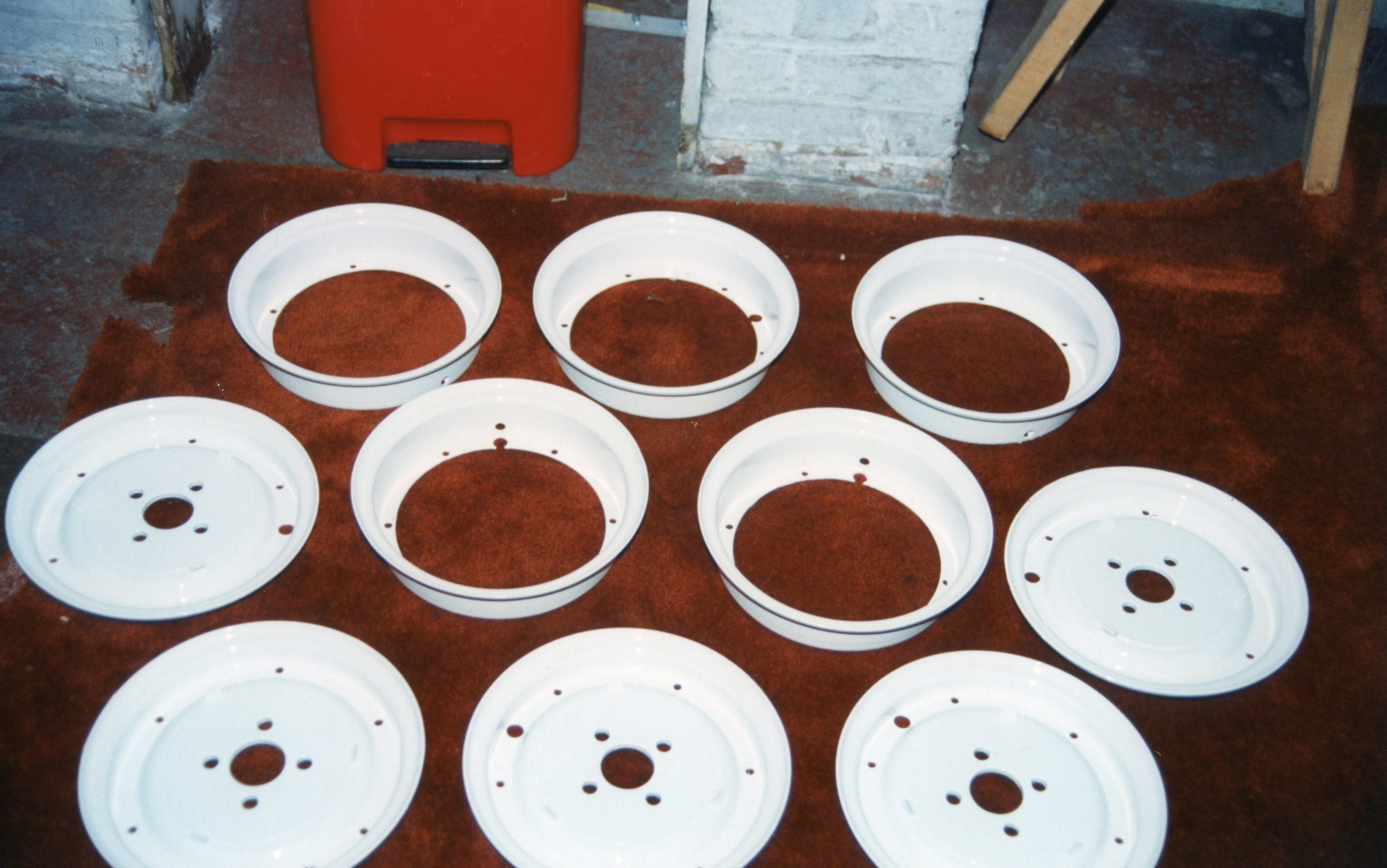
Here’s the truth: ALL U.S. spec Isettas had four wheels and tires (as did the original design). When viewing the car from the rear, it could appear that there was only one rear wheel, as the two rear wheels were only 20 inches apart. They rode on a solid axle, without a differential. This meant that there was no “differential action” on turns. (In a turn, the inner wheels travel a shorter distance than the outer wheels. A differential allows each rear wheel to rotate at a different speed to account for this.) In an Isetta, this lack of differential action meant that there was some tire scrub in turns, hardly noticeable to the driver when 13 horsepower are providing motive power.


Unlike the transmission rumor, though, there was a nugget of truth regarding the 3-wheelers. In Great Britain, Isettas were built locally under license (as they were in France, Brazil, and other countries). The UK had a motor-vehicle structure that labeled 3-wheeled vehicles as motorcycles. Such vehicles only required a motorcycle license to operate on public roads, and were taxed at a lower rate. The Brits took advantage of these loopholes and created a 3-wheeled version of the Isetta. I’ve never seen one in the metal, but in photos, it looks like the thing is about to tip over. And you thought the versions with two rear tires only 20 inches apart looked unstable….


Chain reinstalled into painted case

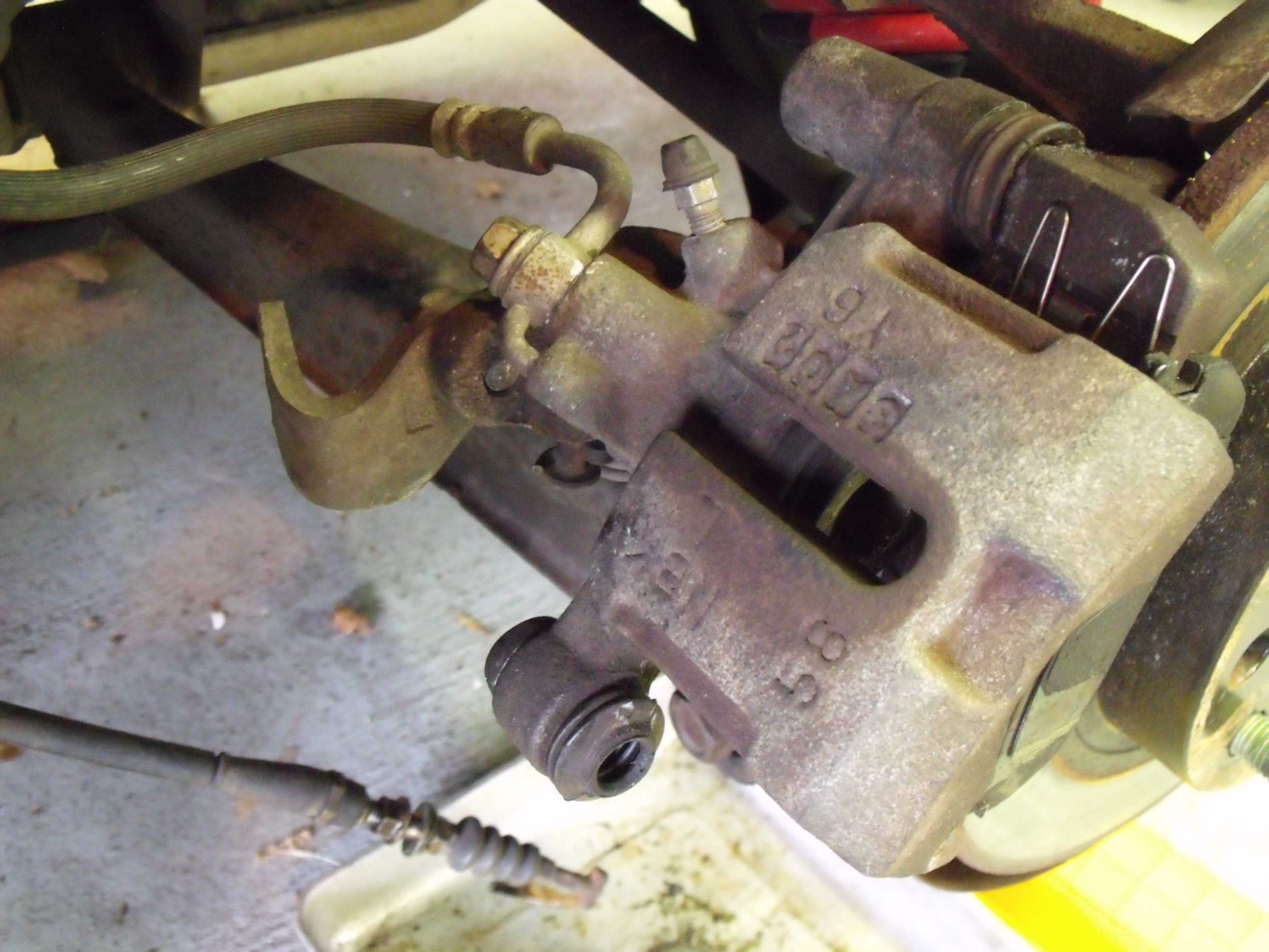
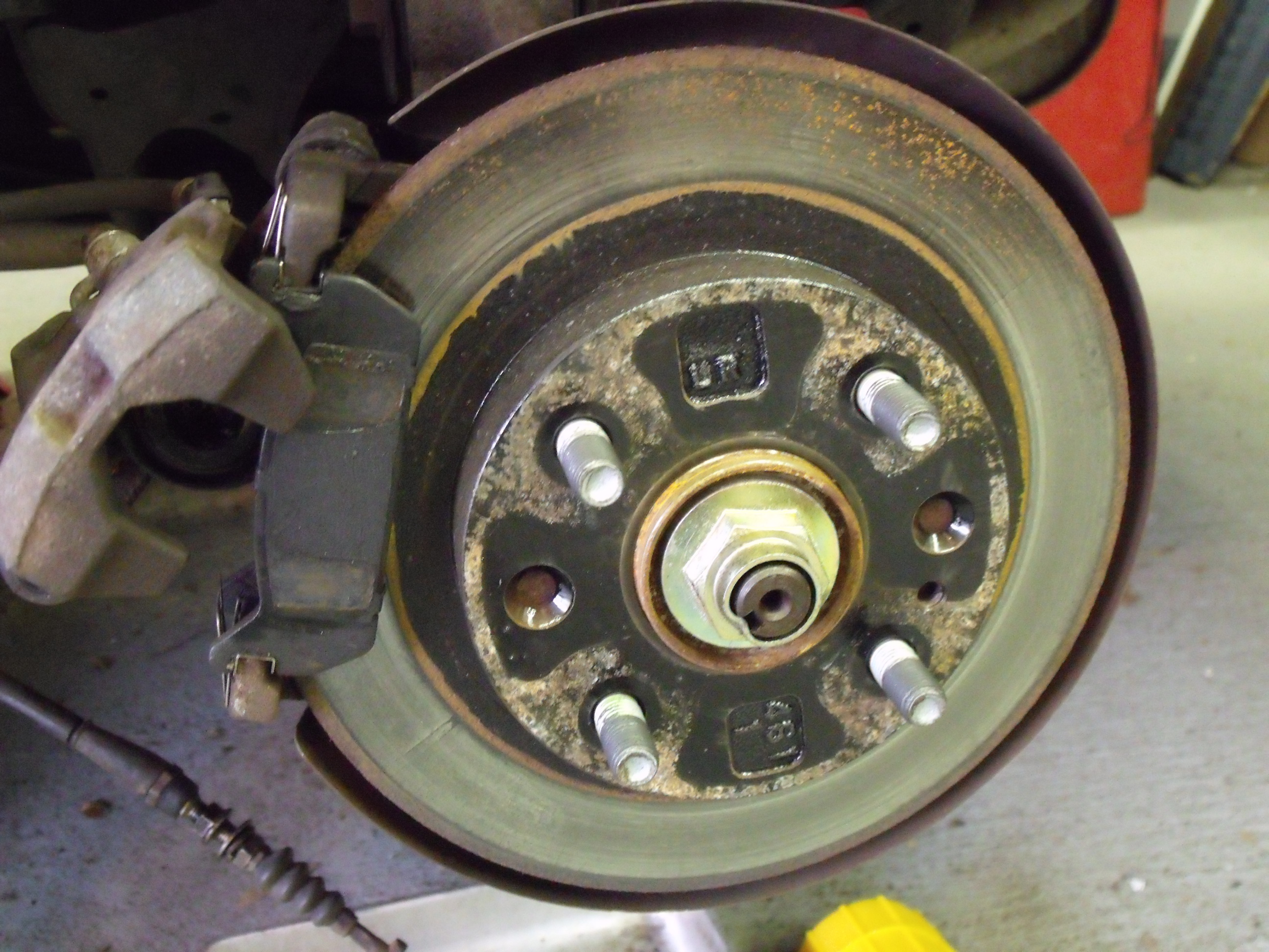
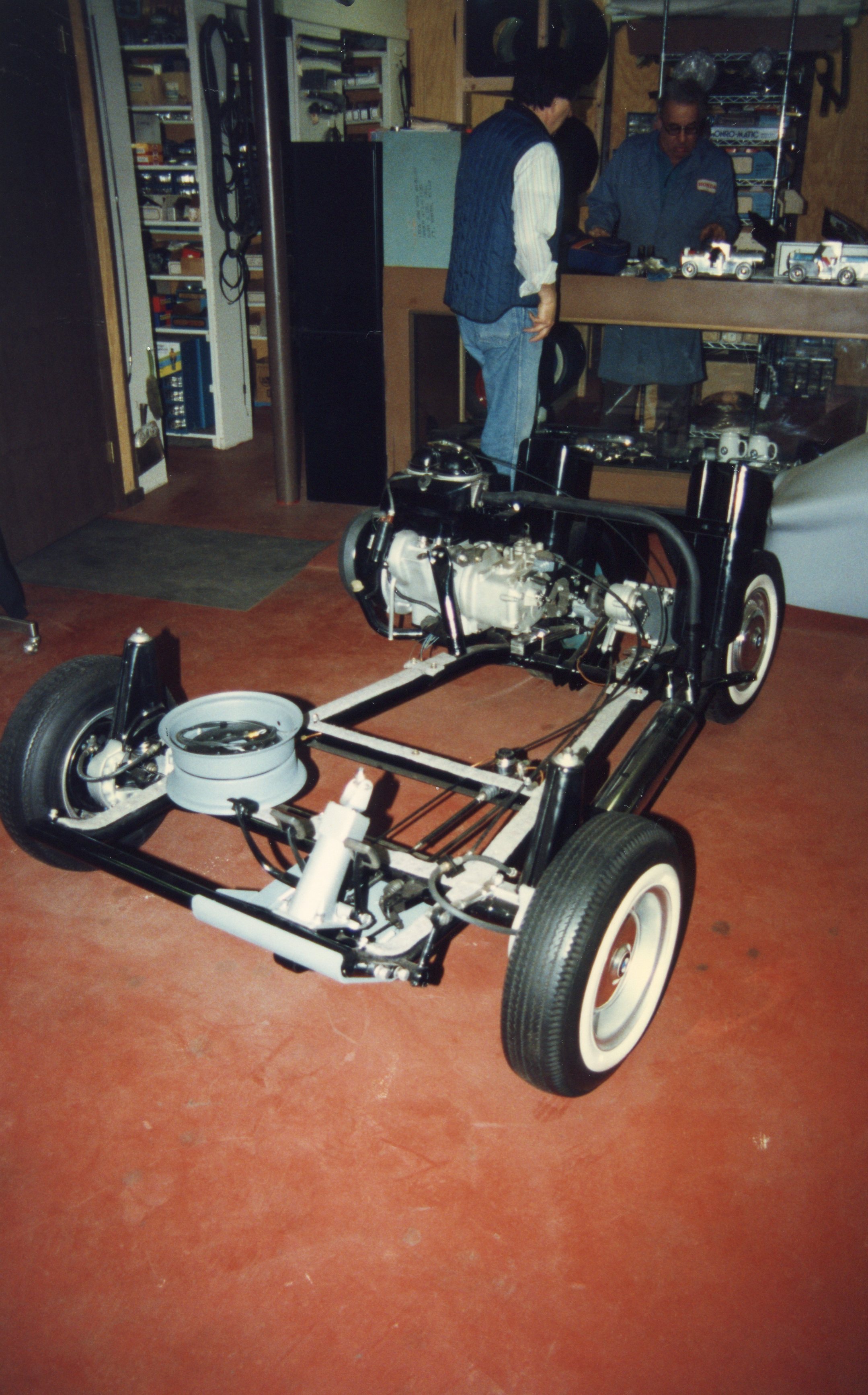
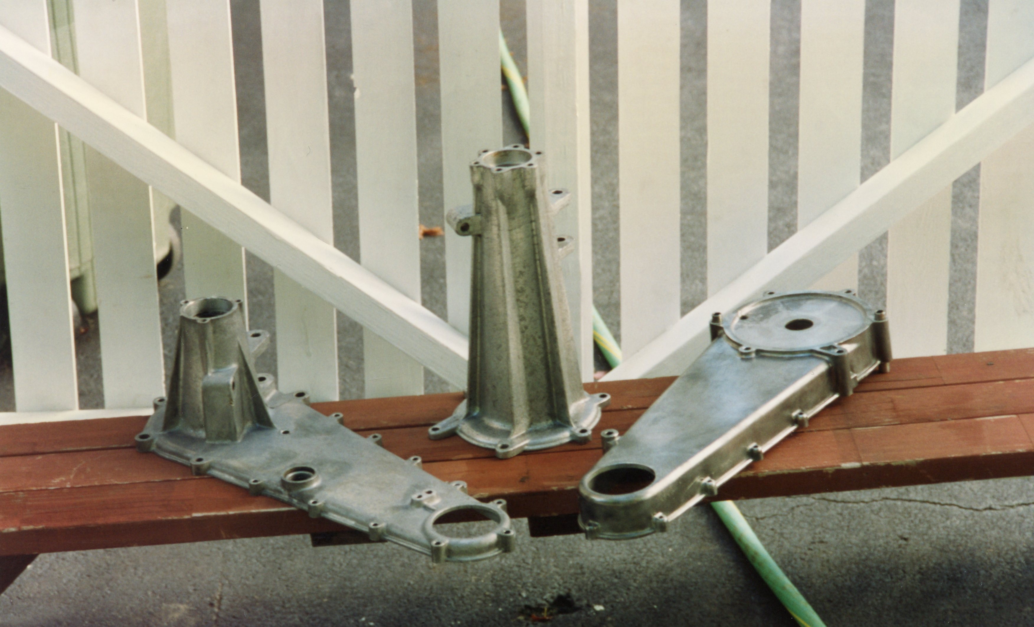
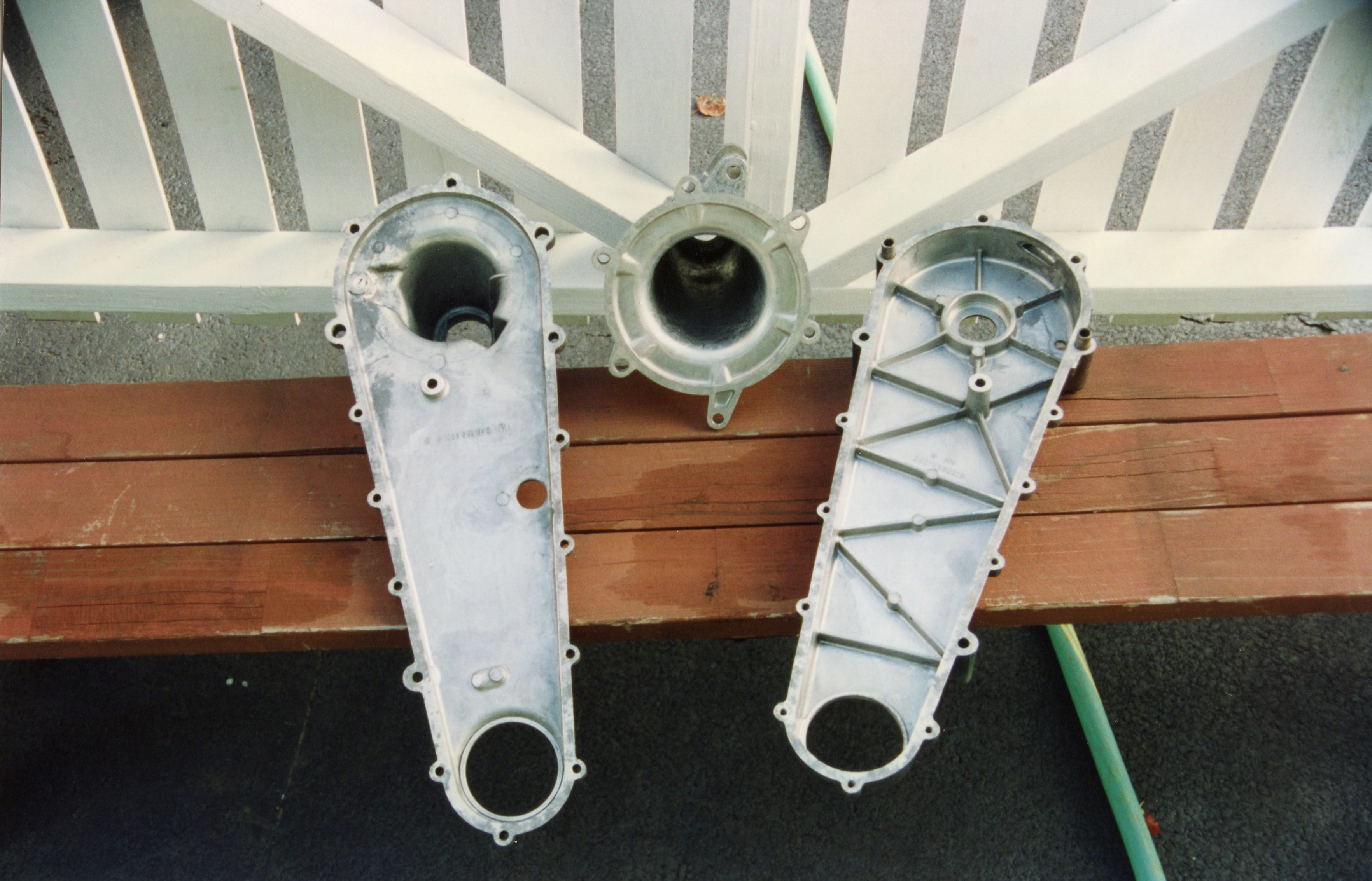
The Isetta drivetrain included the following: a one-cylinder engine, with a four-speed transmission bolted directly to it; an extremely short driveshaft, with a Giubo joint at each end to allow for flex, connecting the gearbox to the rear axle; and a rear axle assembly with a chain drive enclosed in an aluminum housing. The chain drove a solid rear axle, with a 10-inch wheel & tire assembly at each end. The solid axle meant that only one brake drum was needed at the rear. Overall, this drivetrain was light, took up little room, and easily fit into the rear of the chassis.

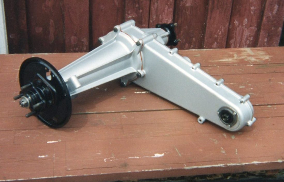
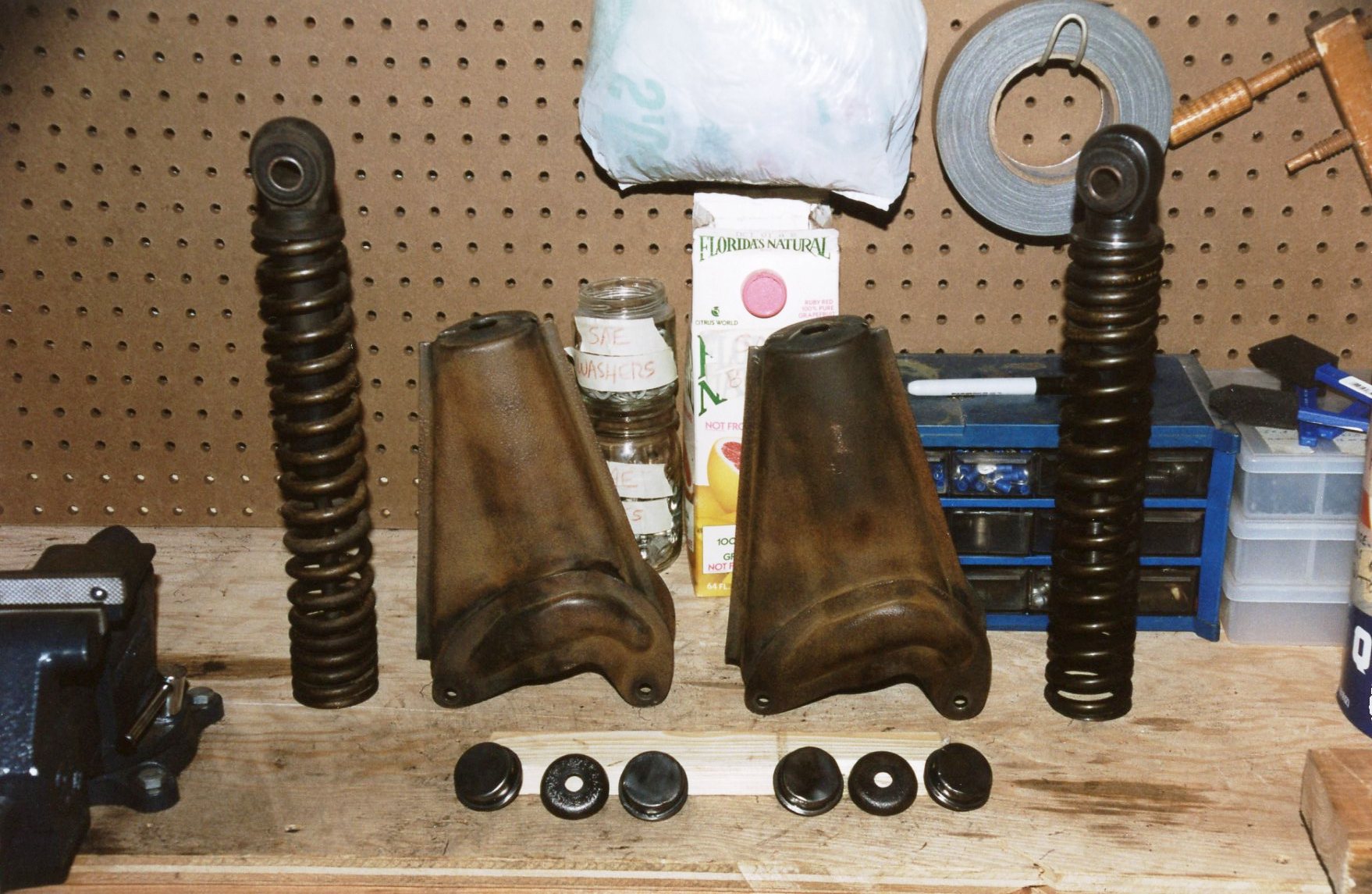
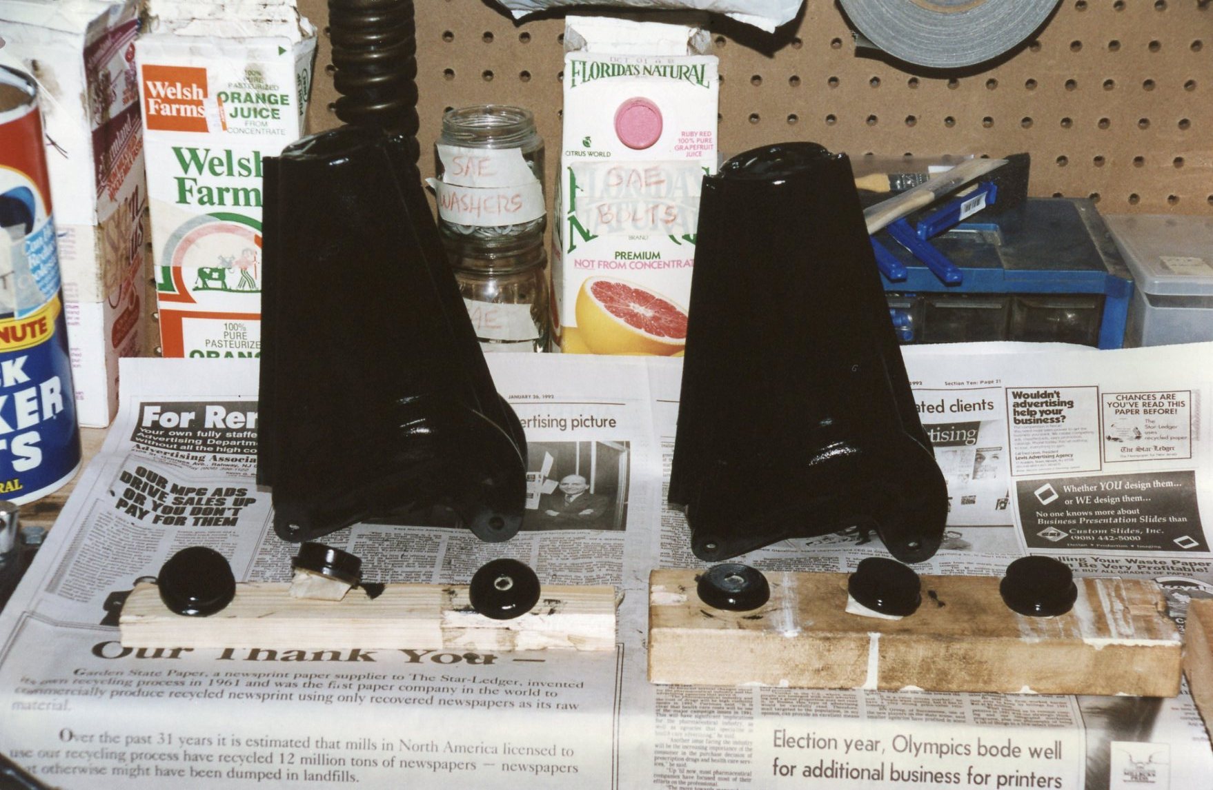
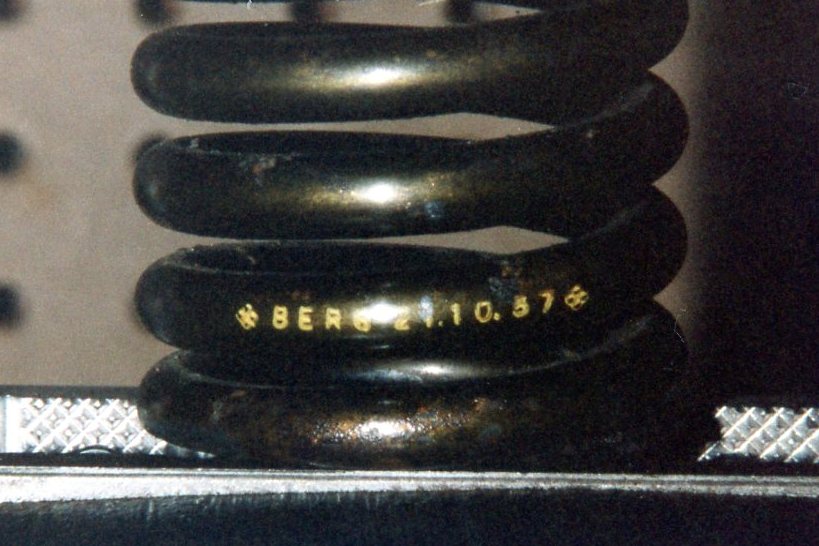
My chaincase was opened, disassembled, and cleaned. Roller bearings were replaced, and the bare case was sprayed with the same high-temp aluminum paint as was used on the engine and gearbox. The chain showed no sign of wear, so I reused it. The case was reassembled, with the freshly painted black brake backing plate making a nice contrast to the silver. The quarter-elliptic leaf springs were treated to the same routine: disassemble, clean, paint, and reassemble. I became aware that except for complex assemblies like the engine, much of the remainder of my car was undamaged, and suffered only from disuse and poor storage.

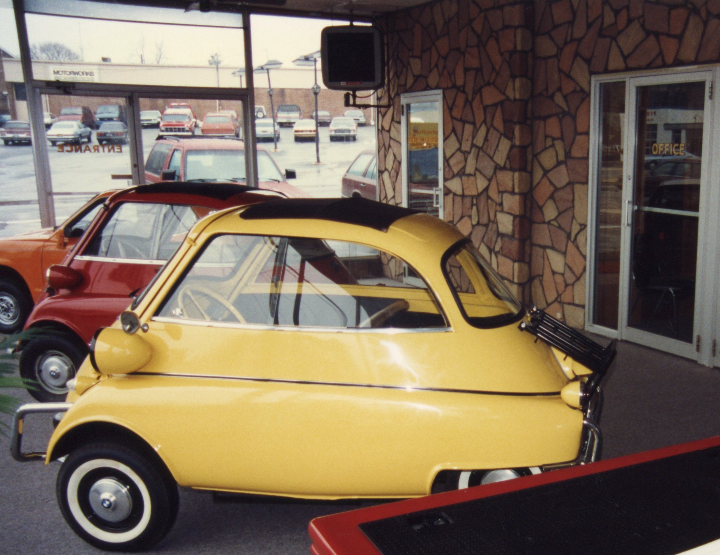
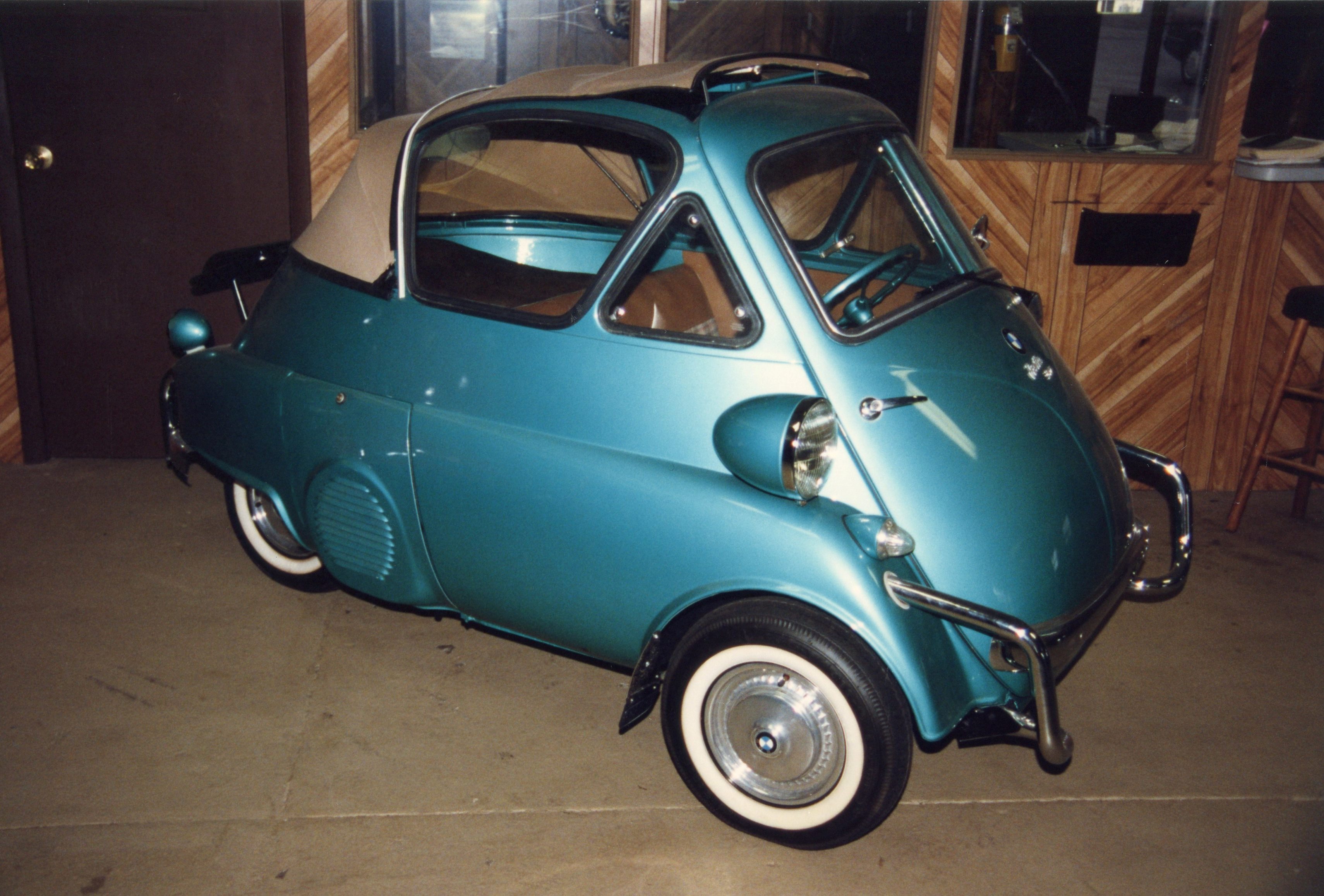
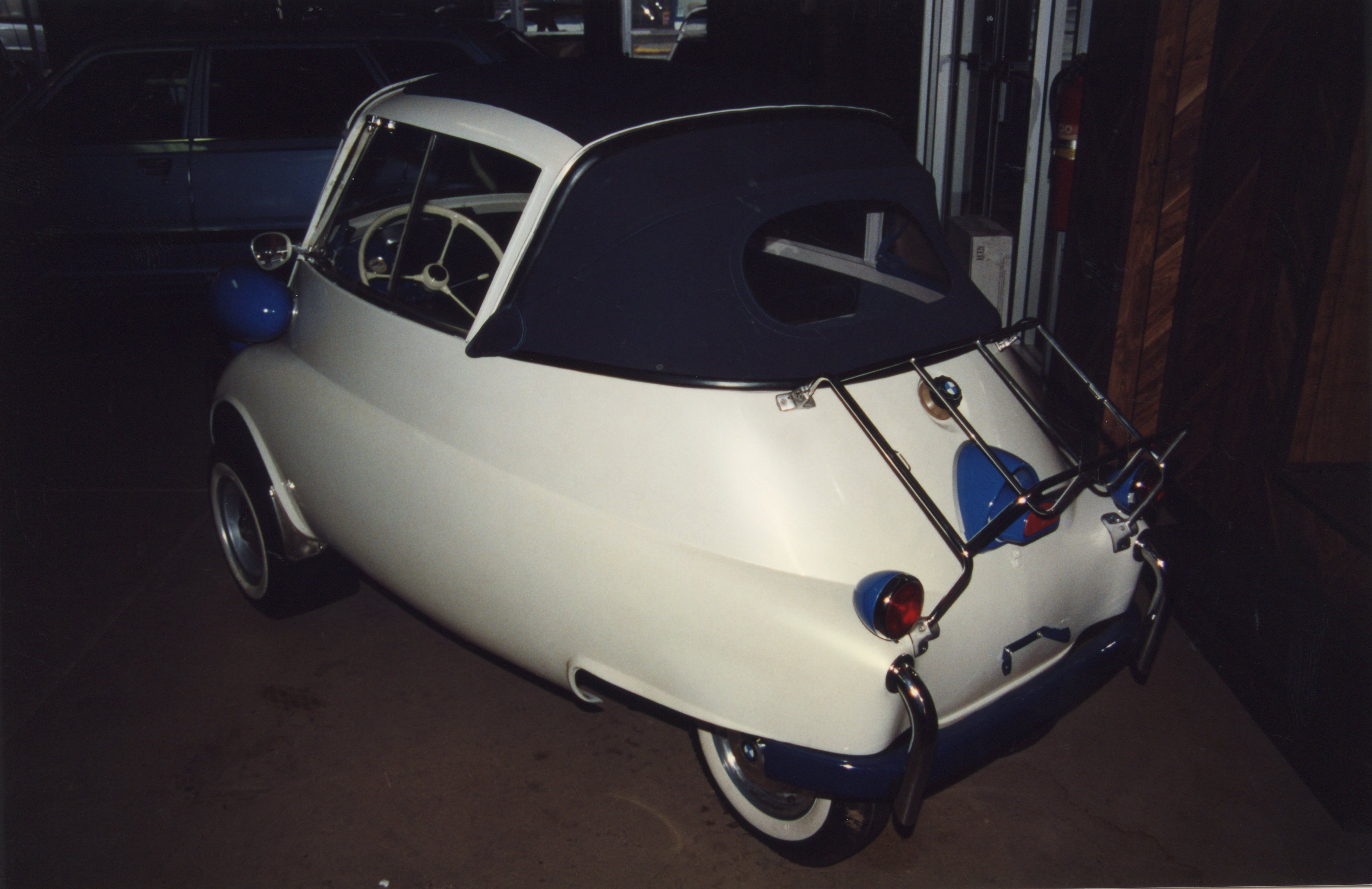
Depending on the state of my garage (which housed my ’67 Dodge Dart convertible, and also was used for various house projects), the Isetta bodies would occasionally need to be moved out of the garage, then back into the garage. The bodyshell with glass can easily be lifted by three people. It became an inside joke among my neighbors when I came knocking, asking for their help to relocate a body.

Body on its way back into the garage

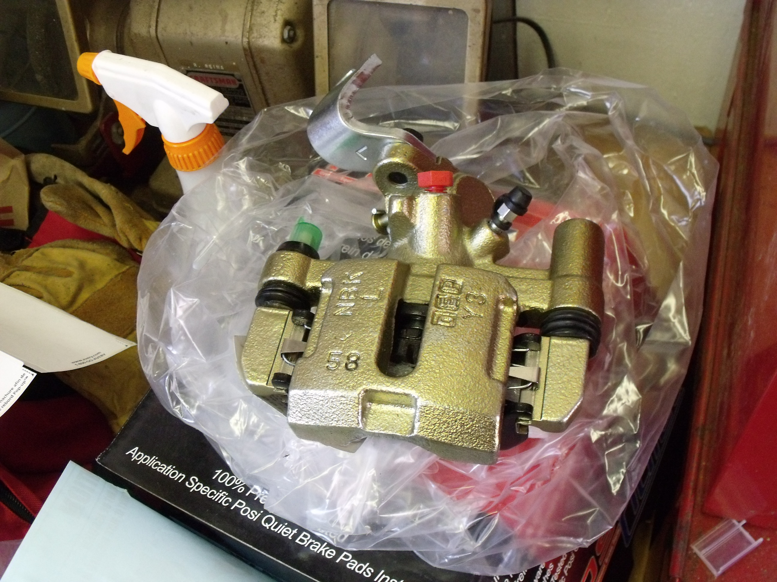
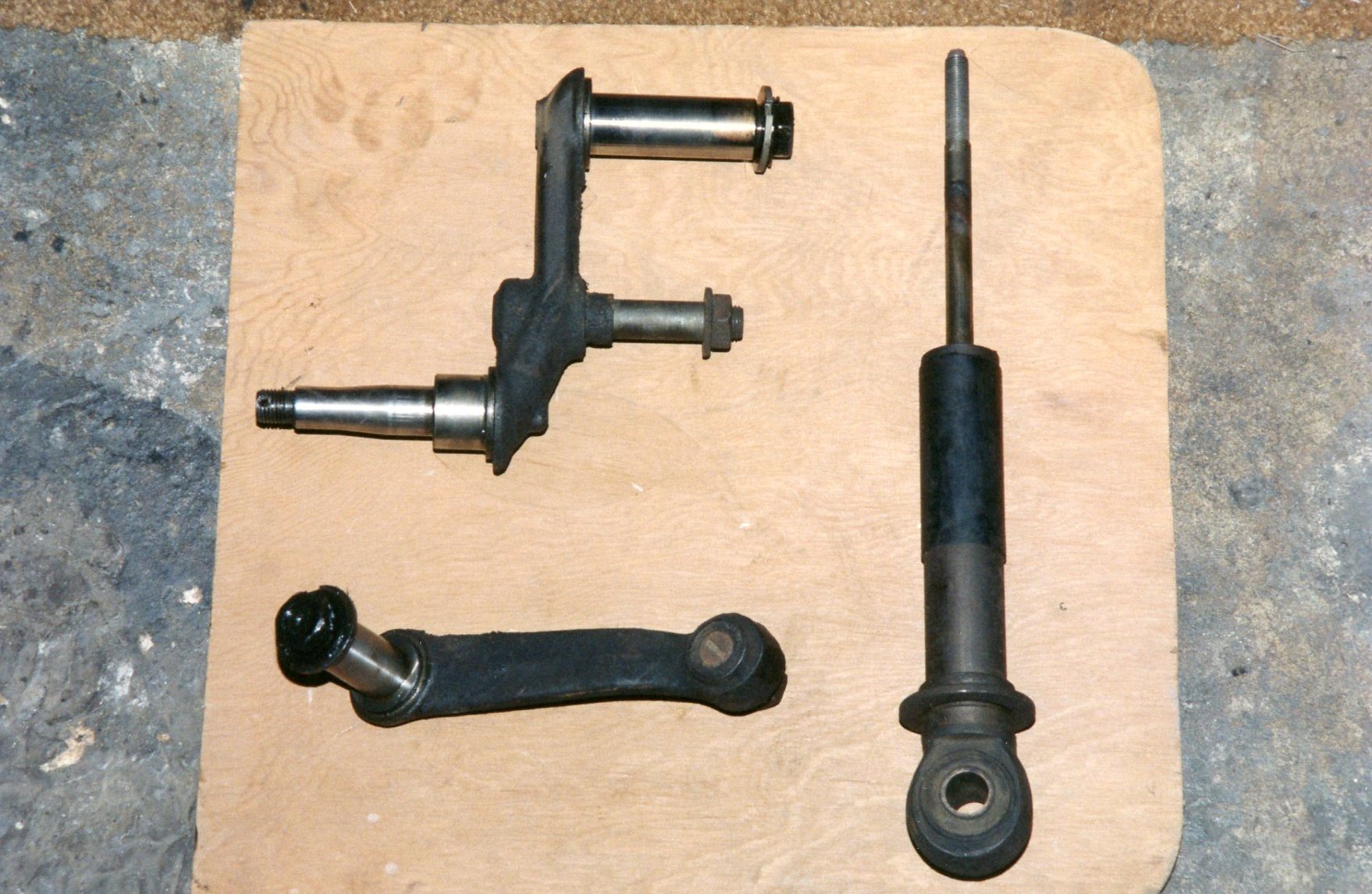
All of this drivetrain work took place throughout 1993 and 1994. What was left? As mentioned earlier,  I was on the hunt for a qualified machine shop for the cylinder heads. The finished rear axle meant that the chassis was close to rolling on its own four wheels, after which, there were still brake lines and pedal connections to contend with. Even though I didn’t plan to perform my own body and paint work, I thought that I could restore the driver’s controls (steering wheel & column, pedal assembly, and other interior components) myself.

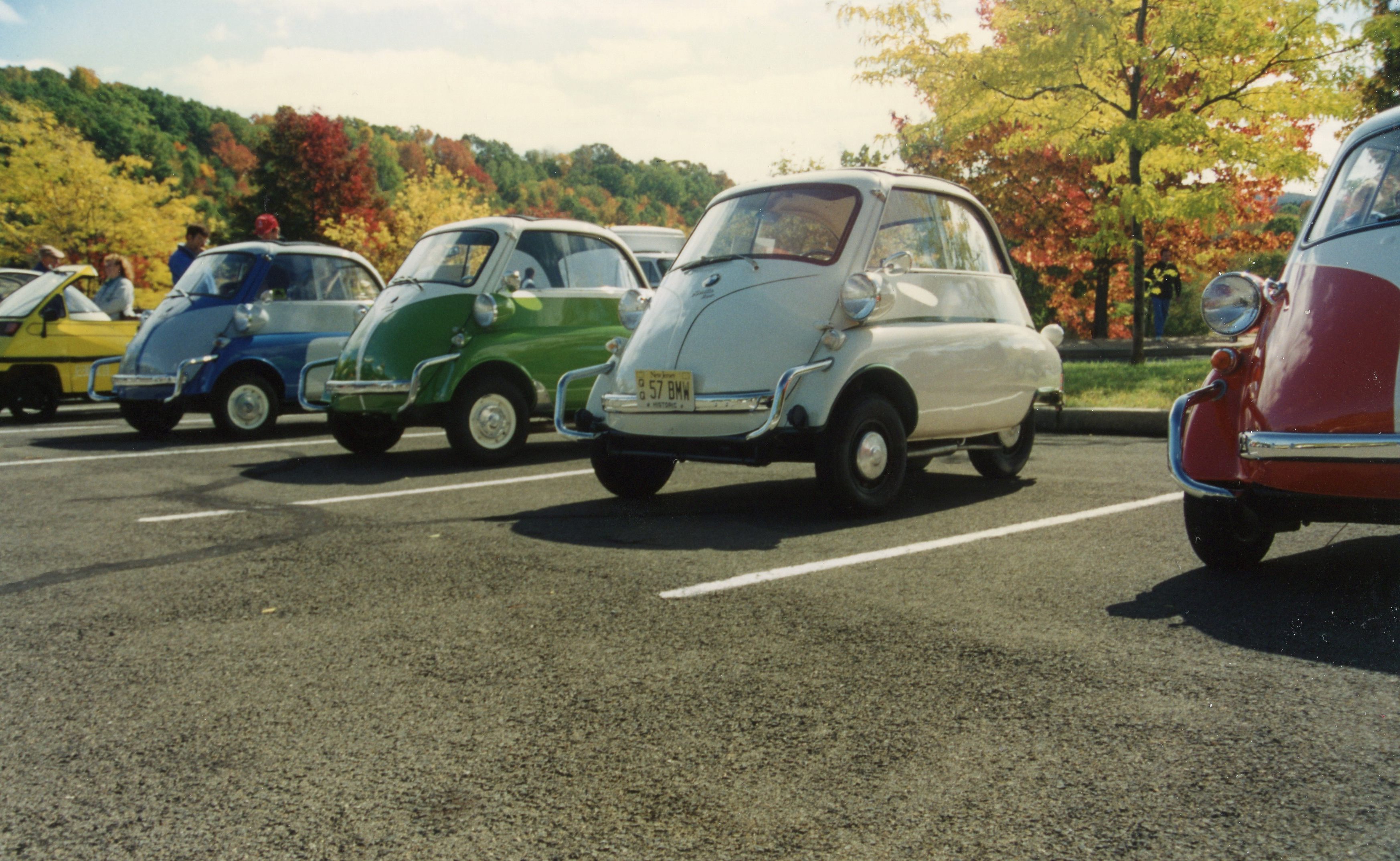
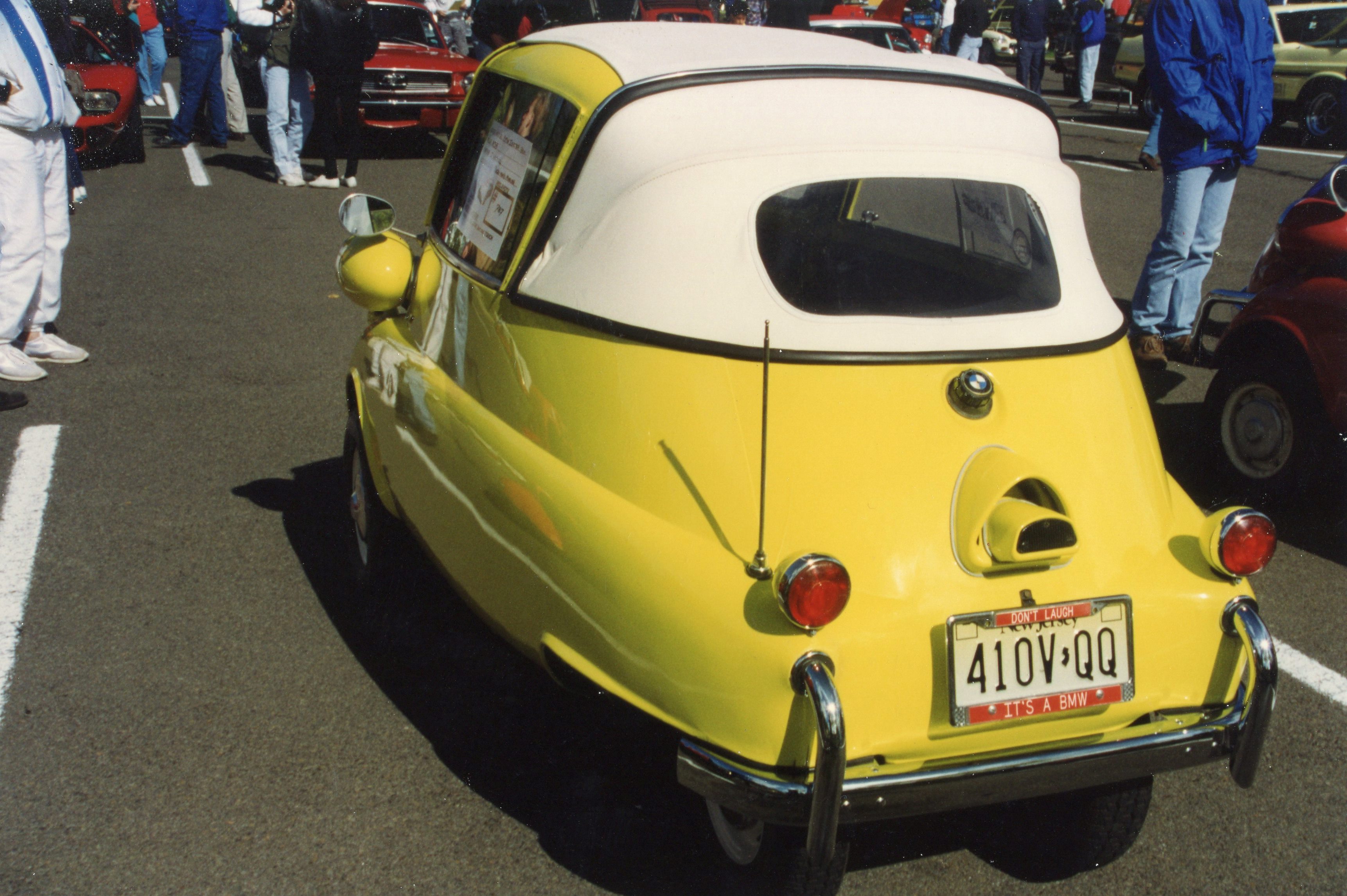
The year 1993 also afforded me the chance to attend two different car shows featuring Isettas. One show was the now-famous Bubble Car Show in Laurel MD, where I had been in attendance in the early ‘80s. I got reacquainted with my microcar buddy John Malcolm there, and followed up my visit by placing a parts order with him.

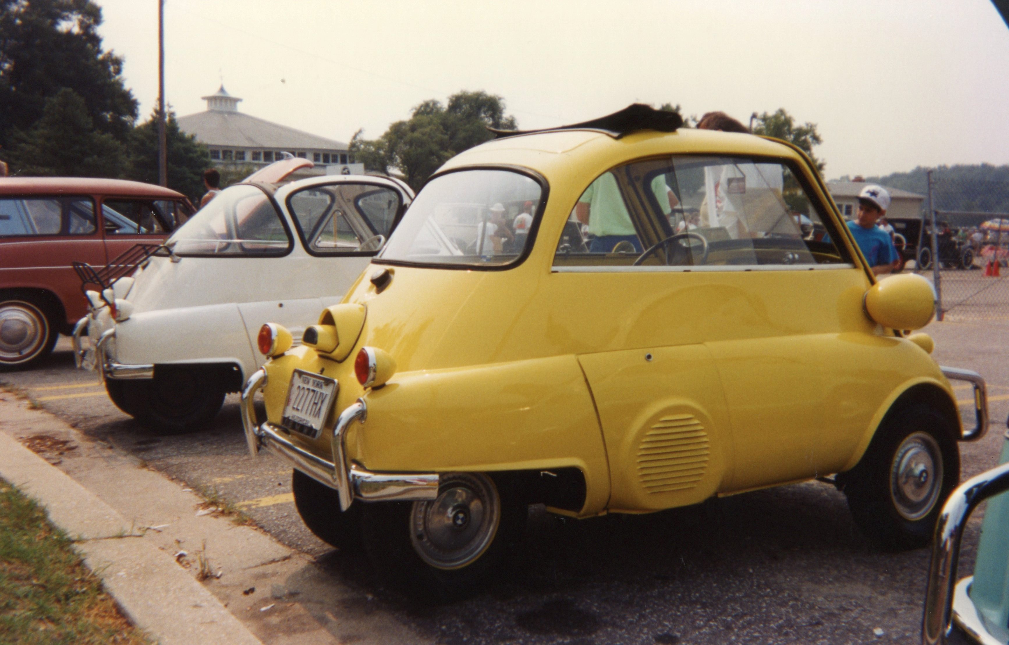
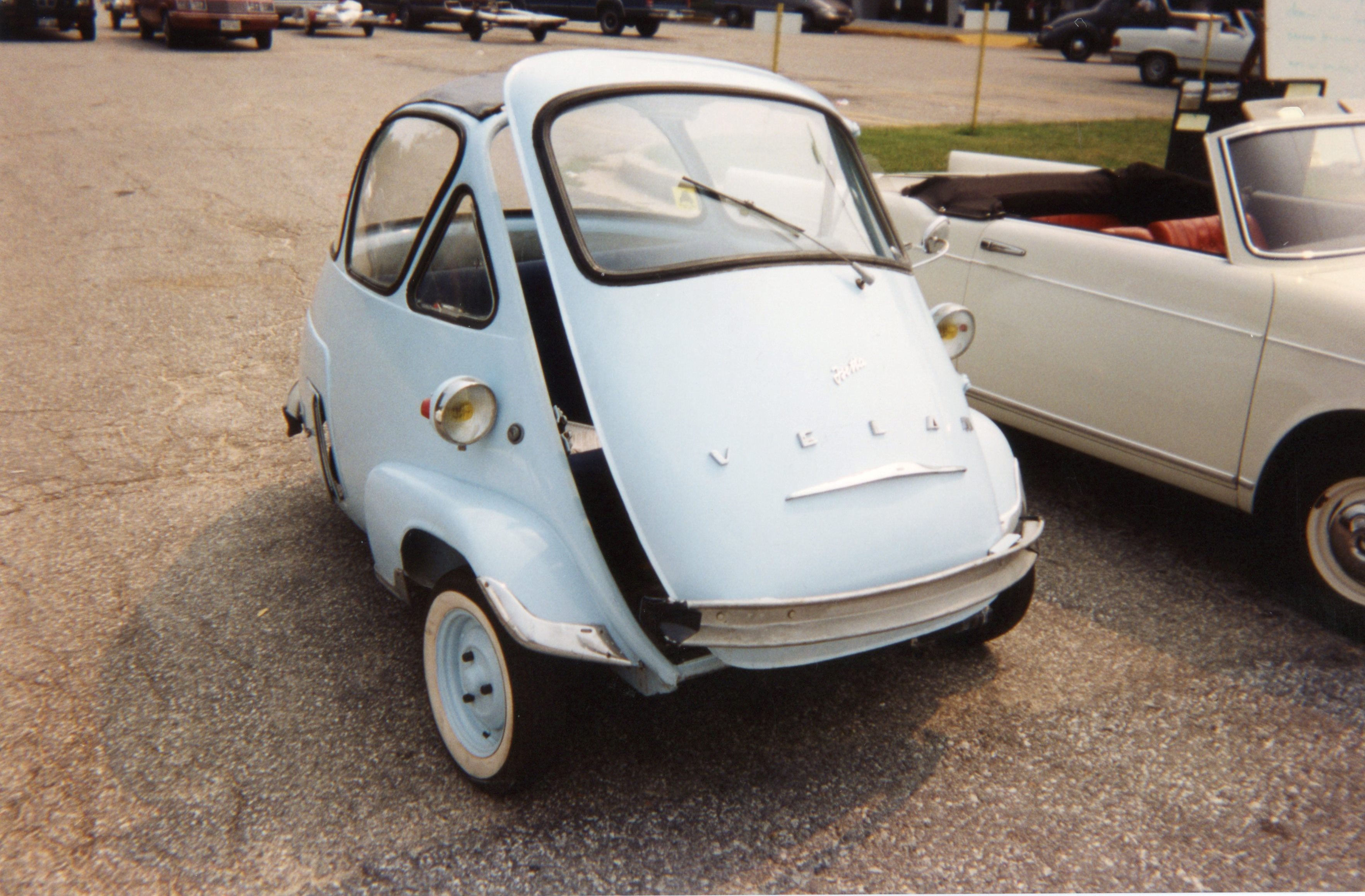
Later that year, and a bit closer to home, the annual TVR car show, held in western NJ, included a special class for microcars (what connection they have to TVRs is lost on me, but it was nice to find Isettas within a 45-minute drive). Both shows provided further motivation to keep pushing myself.

The goal hadn’t changed: “The Isetta will drive in ‘95”. The unanswered question remained: “While I’m making progress, is the progress moving fast enough?”

Next time in the Isetta Saga: further engine progress is made, and we host the first of what will be several parties, to celebrate a certain milestone. It’s kind of corny, but hey, any excuse to pop open a bottle of champagne. 

All photographs copyright © 2018 Richard A. Reina. Photos may not be copied or reproduced without express written permission.


FUN FACT OF THE WEEK:

SKF, a leading manufacturer of ball bearings, was founded in Sweden in 1907. According to Wikipedia, they are the largest bearing manufacturer in the world. In the 1920s, SKF decided to begin automobile manufacturing. For the car’s name, the company used a word for which they already held the trademark. The word is Latin for “I roll” (as in, roller bearings). That Latin word is “Volvo”.


New Rear Brakes for the 1993 Miata

If your memory is good, you may recall that way back in December of 2017, I filed a blog post entitled “Winter Storage, and the Start of the Miata’s Next To-Do List”. Somewhere in there, I wrote words to the effect that “should we have a mild winter, I’ll be attending to some maintenance, repair, and detail items for the Miata”.

Maybe I jinxed things.

While certainly not a terrible winter, it was plenty cold; too cold to spend much time in the unheated garage. But the calendar claims that spring is around the corner, even if the thermometer has yet to catch up. A few weeks ago, cold or not, I decided to forge ahead with the car’s #1 priority: the replacement of the rear brakes, including pads, rotors, and calipers.

Old caliper looks crusty; can’t see it, but piston is stuck

The Mazda’s parking brake has been loose for a while, requiring a long pull of the handle before it would engage. Attempts to adjust it were for naught. It turned out that the piston in one of the rear calipers couldn’t be adjusted in either direction. Unlike the European cars I’m accustomed to, this Mazda’s e-brake operates directly via cables on the brake calipers, moving the pistons inward to contact the pads and apply the hand brake. Each rear caliper piston should be able to be rotated inward or outward as an adjustment.

Rear rotors are original; while not shot, they’re worth replacing while new calipers are going on

All my Volvos used a set of parking brake shoes inside the ‘hat’ of the rear rotor, in essence giving you a drum brake within the disc brake. While it has its advantages, I’ve seen cases where the e-brake shoes rust and seize inside the rotors. When that happens, your first tool of choice is a large hammer, and the repair procedure reverts to incessantly beating on the rotor to free it from the shoes.

Parking brake cable was easily removed once adjustment nut was loosened

But back to the Miata. I ordered parts through my place of business from Centric. I had my choice from a number of reputable brake parts suppliers, and I chose Centric after learning some detailed information from one of their reps. He informed me that if one orders the LOADED calipers (with pads installed), the calipers receive an anodized finish, compared to the SEMI-LOADED (hardware but no pads) ones, which are cleaned, but are left with a bare metal finish. All the calipers are remanufactured (‘reman’) units, and carry a core charge, refunded once the old parts are returned.

New (actually, remanufactured) caliper is a thing of beauty

I also stepped up for higher-quality rotors which have a black e-coating on the non-contact surfaces, to prevent rust. All the parts arrived last week, and initial inspection showed that everything looked copasetic. In order to get my core charge refunded ASAP, I used this most recent weekend to install the calipers.

Picture show black rust-preventative coating on rotor non-contact surfaces

Once the order was placed, but before the parts arrived, I removed the parking brake cables, and loosened all the caliper bolts, including the hydraulic lines, to ensure that I’d have no surprises during installation. Centric makes a big deal about reinforcing the message to the customer that the core return must include the caliper and parking brake brackets. I’d presume that would be obvious as they are included on the reman caliper, but perhaps not.

The job could not have been more straightforward. Centric even provides new banjo bolts and copper o-rings for the hydraulic fittings. Starting with the left side, I bolted everything up, but had a slight drip from the brake line. It turned out that one of the old o-rings was stuck to the line, and I hadn’t seen it. Once I removed it, everything snugged up and stayed dry.

Newly installed caliper and rotor on left rear

Then I had the exact same problem on the right side, only there was no double o-ring in the way. To stop the drip, I had to resort to reusing the old o-rings. For some reason, the new o-rings are ever-so-slightly larger than the old ones. While it’s good for now, I will get to the store and buy new copper o-rings to make sure that I’ve got fresh ones installed. I’m still not sure why it’s leaking with the new o-rings, but I can get back to that later. Both old calipers, with the necessary brackets, are off the car, and are boxed up and ready to be shipped back to Centric, which I’ll attend to this week.

In the meantime, I placed an order for Valvoline “synchromesh manual transmission fluid”, which comes highly recommended for my five-speed by the guys and gals on the miata.net forum. Weather permitting, I’ll tackle that next weekend.


Looking for the next installment of the Isetta Saga? So am I. Once I find it, which should be during the upcoming week, I’ll spiff it up and get it online for your reading enjoyment by next weekend.


All photographs copyright © 2018 Richard A. Reina. Photos may not be copied or reproduced without express written permission.


FUN  FACT OF THE WEEK:

The first-generation Miata, known as the “NA” version, was launched in 1989 and sold through 1997. Mazda sold over 400,000 units, a runaway success by anyone’s definition.

The Isetta Saga, Chapter 8: Focus on the Front End

In Chapter 7, after figuring out how to take an Isetta engine apart, I did exactly that. With the help of my new Isetta buddy Ron Krause, it was hoped that someday I’d figure out how to get it all back together too.

This chapter of the Isetta Saga quite literally ties together all the pieces that make up the front end of the chassis. We get our first glimpse of something that looks like it might drive down the road (you’ll need to squint).


We had seen in Chapter 6 that the restoration work really began with stripping, cleaning, and repainting the bare chassis. Part of that process included removing all ancillary components from it: springs, shocks, brakes, and cabling. However, moving onto engine work didn’t mean that progress had ceased on the chassis. Parallel progress was being made which would get the chassis back on its four wheels again.

As a way to keep the project moving forward, I would work on several sub-sections of the car at a time. While I was waiting for the paint to dry on Part A, I was disassembling Part B. And while searching for replacements for the broken bits for Part C, Part D was soaking in Liquid Wrench because its bolts wouldn’t bust loose. And so on. Keeping this from disintegrating into a disorganized mess was helped by my infatuations with labeling and photographing everything. Hence, we have the photos I can share with you some 25 years later.


  • SUSPENSION

The Isetta’s suspension was somewhat conventional, employing coil springs over tube shocks encased in housings (a crude coilover) in the front, and quarter-elliptic leaf springs in the rear. In disassembling the front end, I noted that the springs and shocks seemed to be in good shape. The fact that there were no available replacements may have played a small role in my determination that these parts were “serviceable” and could be reused.

The springs had a 1957 date code on them, which meant they were factory original. They looked good, and I would guess that a 770 lb. car wouldn’t exert that much wear and tear on them.

Date code looks like 21.10.57 – late ’57 production car?

One tricky part to the front end were the knuckles, which were designed to hold a small quantity of high-viscosity oil in them. The moveable parts of the suspension, which were the spindle and the swing arm, were lubricated by this oil. The fluid was held in place via metric-sized o-rings. Since I found ZERO trace of existing o-rings upon disassembly, I knew replacements were needed, and I was able to source the correct-size o-rings from one of my suppliers.


  • WHEELS

Most (but not all) Isettas made use of two-piece split rims, with the wheel halves held together with simple nuts and bolts. This arrangement required the use of inner tubes. One of my parts sources had the correct 10” tubes with the correct 90 degree valve stem. Although I had planned to let a professional body shop paint the wheels, I thought I could save some costs by sand-blasting them myself. Jorgen Carlsson, a Swedish engineer I met at work, happened to have his own sand-blasting cabinet, and lived not far from the office. How convenient. I loaded up the wheel pieces and headed over at the end of the work day.

Dirty wheel halves in the back of my Volvo 245

Having never used a sand-blaster before, I imagined the process as similar to painting: aim the nozzle, squeeze the trigger, and viola, old paint and rust are wiped away. Well, not quite as simple as spraying on a new coat.

Ola Paulsson and Jorgen Carlsson

While the blast of sand does bring the part down to bare metal, it is a very slow process. The gun must linger on the spot for several moments, after which, there is only a small area cleaned. You then aim for the adjacent spot, as you clean off an area maybe the size of a quarter every few minutes.

Preblasted wheels on left; blasted wheels on right

There were 10 wheel halves (including the spare), and each piece needed to have both sides worked. I thought I’d be there for an hour or two; my recollection is that it was a very late night for me. Once I started, I felt I needed to finish it, and in actuality, the whole job probably took 4 or 5 hours. Jorgen was extremely patient with me, letting me stay until my work was done.

Took 5 hours, but all wheels are cleaned down to bare steel

The newly-blasted wheels were taken to a body shop local to the office, with my instructions to “paint them white”. They did, and I picked them up later that week.

Freshly painted wheels are bright white

Next came a very controversial decision among my friends: were the wheel bolts supposed to show the BOLT HEAD or the NUT to the outside of the wheel? Remember that I had two chassis, and two sets of wheels. As I had received them, ALL the wheel hardware showed the NUT on the outside. There was no proof that the factory assembled them that way; but I had a hard time believing that all these wheels had had the hardware reversed. That’s how I reassembled the wheels, in spite of the razzing I got from more than one friendly “expert”.


  • TIRES

When BMW sold new Isettas in the mid-to-late ‘50s, they left the factory with 4.80 x 10 bias-ply tires. Radial tires were around in the 1950s, but very few cars were so equipped. While I certainly had taken a strong turn toward originality for my restoration, I also intended to drive this car, and based on that, I was wanted to install radial tires, for safety, handling, and comfort, judges be damned. The equivalent size was a 145SR-10, and Michelin manufactured a ZX tire in that size. A contact inside Volvo was able to get me a set of 5 Michelins at a very favorable price (my handwritten notes say that I paid $26.67 per tire). The split rims meant that I could mount the tires myself.

Brand new Michelin ZX, 145SR10, label still attached

  • IT STARTS TO COME TOGETHER

The front suspension was easy to put back together (I made my own coil spring compressor from some threaded rod and steel strapping), and once that was assembled, two of the completed wheel-and-tire assemblies bolted right up to the chassis.

OH YEAH!

The grin on my face says it all: with about two years of somewhat sporadic work behind me, THIS moment felt like a giant leap: the chassis was again rolling, if only on its front wheels. The back half of the car was still a challenge, as that is where the drivetrain sat: even with the engine work coming along, I still had to get to the gearbox, rear axle, and rear suspension. But progress is progress, and as I gaze at this photo again, I’m reminded how this milestone pushed me to keep at it.

In our next installment (what am I up to, Chapter 54?), two engines get built up courtesy of the rebuilt cranks of Ron Krause; and the rest of the drivetrain is tackled, as the man with the toolbox rebuilds his first-ever manual transmission. Hey, it’s just a box full of gears.

All photographs copyright © 2018 Richard A. Reina. Photos may not be copied or reproduced without express written permission.


FUN FACT OF THE WEEK:

The Michelin Tire Company, founded by brothers Edouard and Andre Michelin, is responsible for two major tire innovations: the invention of the removable pneumatic tire in 1891 (prior to this, pneumatic tires were glued to the rims and were difficult or impossible to repair); and the invention of the radial tire in 1946.

The radial tire gained almost immediate widespread adoption in Europe. But the U.S. car makers stubbornly stuck with bias-ply tires (U.S. market share of bias-ply tires in 1967 was 87%). That changed when in 1968, Michelin opened its first U.S. sales office, and Consumer Reports magazine reported on the superiority of the radial tire.

The Spring ’18 Car Show Calendar is Filling Up Quickly!

With spring just around the corner (the calendar says next Tuesday, even if I spent part of this morning clearing some residual snow from last week’s double-whammy storms), I realized that I had been remiss in updating my own “Calendar of Events”.

Covers coming off soon!

We car guys and gals patiently wait for those final traces of salt to be washed away so we can unhook the Battery Tenders, check fluid levels and tire pressures, and ease our old iron out into the early spring sunshine. It’s nice to be reminded that there will be plenty to do; here’s what’s on my calendar so far (and this is just the first two months of the season):

Be sure to check this page frequently. Once show season starts, I’ll do my best to maintain this page and let you know what’s happening in the area.

All photographs copyright © 2018 Richard A. Reina. Photos may not be copied or reproduced without express written permission.

The Isetta Saga, Chapter 7: The Art & Science of Isetta Engine Disassembly

In Chapter 6, we saw in pictures and words how the chassis was the first component to be transformed from rusty hulk to freshly painted beauty (if an Isetta chassis can be beautiful).

In Chapter 7, we discover the secrets to taking apart what is essentially an air-cooled BMW motorcycle engine. Then we do it two more times.


 You cannot embark on a project of this magnitude and expect to do it alone. This is especially true for tasks you’re performing for the first time. At some point, there will be the need to rely on, and to seek expertise from, those who have done these things before you. This is the theme for this Chapter, and this concept will certainly be revisited again.  

 I’ve related in earlier Chapters how glad I was to discover other hobbyists who were Isetta restorers and collectors. There was some knowledge-sharing, and just as important to me, there was satisfaction in knowing that parts availability could be fulfilled through some of my fellow Isetta fanatics. Now, as I was about to start a mechanical teardown and rebuild, I really needed some assistance from others.

 Two gentlemen who were serving the Isetta community, John Jensen and Ron Krause, were both huge factors in the success I had with my engines. Simply put, this restoration would have faced a far rockier road without them.


With the cleaning and painting of the bare chassis done, I had to decide which mechanical sub-system to work on next: engine, gearbox, rear axle, electrical, suspension, or brakes. Bodywork, which I would not be doing myself, would be postponed until most or all of the mechanicals were completed.

The decision was made to begin with the engine, as that would potentially take the most time. Also, from staring at these engines over the last few years, I still did not know how to take the one-cylinder Isetta engine apart. To be specific, I saw no way to remove the crankshaft & connecting rod from the crankcase. The case was one piece; it was not “split” the way an air-cooled VW or Porsche crankcase is. And as near as I could tell, the bottom of the connecting rod was not split either. At least I couldn’t see or feel any bolts which would hold an end cap in place. Whatever the trick, this was nothing like any other automotive engine I had worked on.

I was now subscribing to Minutia, the quarterly publication of the Microcar & Minicar Club. In a recent issue was an ad from a fellow named John Jensen (I recognized his name from the old HMI Club). He was advertising a book he had authored and self-published (come on, you think Random House was interested?) entitled “Isetta Restoration”. He claimed that the book was a detailed account of the restoration of his own Isetta. It seemed expensive at $42 in 1992 dollars, but I purchased it.

A postcard advertising John Jensen’s “Isetta Restoration” book

The memory of getting the book in the mail and opening it is vivid. The first thing I looked up was “engine disassembly”. I’ll paraphrase what was in the book:

            “The Isetta crankshaft is a two-piece affair, with the two halves pressed together through the bottom of the one-piece connecting rod, which rides on a roller bearing. To remove the crankshaft/con rod assembly from the case, you must heat up the case to a temperature of around 400 degrees F. Doing so expands the aluminum just enough so that you can wiggle the crank/conrod out of the front opening. Be sure to use oven mitts!”

For me, this was as good as “X” marks the spot on a treasure map. I couldn’t wait to try this. But first I needed to make a decision: WHICH of the three engines would I rebuild?

Yes, I was in possession of three engines, all in various states of disassembly. Taking an approach I had already used with the bodies, carburetors, and other systems, I decided to disassemble all three engines, and take stock of what I had. I cleverly labeled the engines A, B, and C. Three cardboard boxes were also labeled A, B, and C, and were positioned under my workbench. As parts came off, they went into their respective box.

Engine B’s oil pickup had been in more water than oil

At first glance, all the engines looked questionable, as they had been open to the elements for many years. With front covers and oil pans removed, the picture became clearer: the ones which kept oil in them looked better, if a bit black. And one looked like it had been lifted from the deck of the Titanic (not really, but it certainly had been in water).

Based on this visual inspection, I decided to rebuild two engines, one for my car, and one for my step-son’s. The third engine would be sold for parts, which would help fund the project.

A colleague at Volvo, Steve Kraitz, was also a part-time carpenter, I showed him a page from Jensen’s book which detailed the construction of a wooden engine stand that could be bolted or clamped to a workbench. Steve gladly agreed to build this for me, charging only for the cost of the wood. That stand was a major help with the engine rebuilds. Because the engines are so small, it was a simple matter for one person (me) to bolt the engine to the wooden stand, and then lift and bolt the stand to my workbench.

ENGINE A:

Engine A on plywood stand, about to be disassembled (stand is bolted to workbench)


Coked black, here are engine A’s chains and sprockets pre-cleanup


Snap-On puller used to pull cam sprocket; wrench stands in for leverage

As engine parts were removed, they were cleaned, labeled, and returned to the appropriate box. I now had three engine crankcases, with everything removed except crankshafts and connecting rods.

Time to fire up the blue torch.

My trusty Bernz-o-Matic was pressed into action. I selected Engine A. With the exterior of the crankcase as clean as possible (I didn’t need to add to the drama by igniting any errant sludge), I moved the flame around the front of the case. The crankcase, of course, was bolted to the plywood engine stand, so I couldn’t get too close to that either! It felt like an eternity, but after about 15 minutes or so of heating, I guessed that the aluminum had absorbed as much heat from a propane torch as it was going to.

I grabbed the oven mitt which I had thoughtfully brought down from the kitchen, grabbed the nose of the crankshaft, and worked it forward. I had to experiment with tilting the shaft to get the connecting rod to clear the opening. It looked like it wasn’t going to come out. Moments passed. The crankcase was cooling off.

POP – I must have blinked, because in the next moment, I was holding onto a crankshaft/conrod assembly OUTISDE the crankcase. Yahoo! I exclaimed (before that was a search engine).

ENGINE C:

A very filthy Engine C assumes the position


Armature off, engine C shows a lot of rust behind the front cover


Engine C’s crankshaft and crankcase separated

I stopped for now. This was too much excitement for one night. I worked on the next two engines on subsequent nights, with the same success. But the next step was still a problem in search of a solution: how was I going to separate the crank halves so that a new bearing could be installed?

The 3 bare crankcases. None showed any sign of wear or damage.

In the early 1990s, Old Cars Weekly was a viable publication in the hobby, and I subscribed to it. The classifieds in the back could be helpful, and it was here where I noticed a vague ad from someone who offered Isetta restoration services. His name was Ron Krause, and he was in Emmaus, PA, only an hour from my house. But first I decided to give him a ring:

RR: Hi, I’m calling to find out if you can rebuild Isetta engine crankshafts.
RK: Sure, just bring me the engine so I can remove the crankshaft and examine it.
RR: Oh, the crank is already out of the case.
RK: Who did that?
RR: I did.
RK: YOU are a genius.

I tried to remain humble at this inference of my intelligence level (really, I was just a tech with a blowtorch). But Ron was OK with me bringing the crank/conrod assembly to him. We agreed that I could drive out on a Saturday morning to drop it off.

The front of Ron Krause’s Isetta “dealership” (note Honda 600 at end of row)

The following weekend, I arrived in Emmaus in front of what looked like an Isetta new car dealership. Out front, there was a glass-walled showroom with several restored Isettas. Inside was a service area with cars-in-progress, along with several chassis. Ron himself was behind a parts counter, assisting a customer ahead of me. It was 1957 all over again.

Ron Krause had been a successful Honda dealer principal. As I understood it, he got into Hondas very early in the game, sometime in the early ‘70s. He prospered through all the boom years, and then decided to retire. He sold the franchise, and the new owners had to relocate when he retained ownership of the property. He kept the building where his Honda dealer was, and turned his hobby into an Isetta business. Here was yet another “character”, as seemed to be the trend among people who liked Isettas (not sure what that said about me).

I had time to wander around while waiting for him to finish with his customer, and I couldn’t help but observe that as nice as his restorations were, they were not done to 100% original standards. There’s nothing wrong with that if that’s what you want, but many of these restorations were not my preference. He especially favored inauthentic colors. A rare bubble-window convertible was a quality job except for its metallic turquoise paint. Not quite as bad was the white sliding-window convertible with blue body accents.

When Ron finally came out from behind the counter to greet me, he also went back to work on one of the chassis. While we talked, he cut an intake manifold in half so that the two halves could be re-welded with one end rotated 90 degrees. Ron made no secret of the fact that he “hated” the factory Bing carburetors. No doubt driven by his long-term Japanese car experience, he said he converted ALL his Isettas to run on Hitachi carbs. The reconfiguring of the intake manifolds was all it took for the Hitachis to bolt right up, at least according to Ron.

Restored chassis in front, Ron Krause in rear (wearing Honda smock)

He agreed to rebuild the crankshaft and con rod assembly for me, so I left it with him, but not before inquiring about other parts he might have. It felt like quite the stroke of good luck to have several sources of Isetta parts (first Isetta Johns in Rutherford NJ, and now Ron Krause) within an hour’s drive of me. Things were looking up in my quest to get this project on the road by 1995.

My signed receipt from Ron Krause, proof that he had my crank


Chapter 8 of the Isetta Saga will detail progress on suspension, wheels, and tires happening while we patiently wait for the Krause crank creations (moan).

All photographs copyright © 2018 Richard A. Reina. Photos may not be copied or reproduced without express written permission.


FUN FACT OF THE WEEK:

Today we take for granted that the Japanese “Big 3” in the automotive world are Toyota, Nissan, and Honda. Toyota built its first passenger vehicle in 1935; Nissan was building cars under the Datsun name around the same time. But Honda started much later: its first vehicles went on sale in 1963.

While it entered the U.S. market in the late ‘60s with some quirky small cars, its first mainstream success was the introduction of the Civic in 1973, which stood out as one of the few front wheel drive vehicles available in any segment. The Accord was introduced in 1976. Both the Civic and Accord have been in continuous production since their introductions in the ‘70s.