Now, the full story as to why I was not able to drive my Alfa to this year’s AROC (Alfa Romeo Owner’s Club) annual convention in Pittsburgh can be told. In my initial post about the convention, I wrote:
Let’s get this bit of disappointing news out of the way: while this Alfista was in attendance, his ’67 Alfa GT Junior was not. Four days before the scheduled departure, the car’s right front brake caliper locked up, and although repair parts were obtained, there wasn’t enough time to effect a safe and sufficient repair. So the green stepnose stayed home.
This is what happened: Four days before we planned to leave for Pittsburgh, I drove the Alfa to my friend George’s house. George (Geo to his really close friends) lives just five miles away, and while he was excited to join in the weekend’s festivities, he had never driven my car before. I thought it only fair that he have a crack at it before we commenced on a 6-hour journey.
As soon as I pulled out of my garage that morning, I sensed that something was amiss. The car seemed a little down on power, and it pulled to the right. Other than that, it drove OK, so I pushed onward. The moment I entered Geo’s driveway and killed the engine, smoke emanated from under the closed hood. I popped the hood but saw nothing obvious. When Geo came out, I explained what had happened, and we both decided to let him drive the car, if only for 2 or 3 miles.
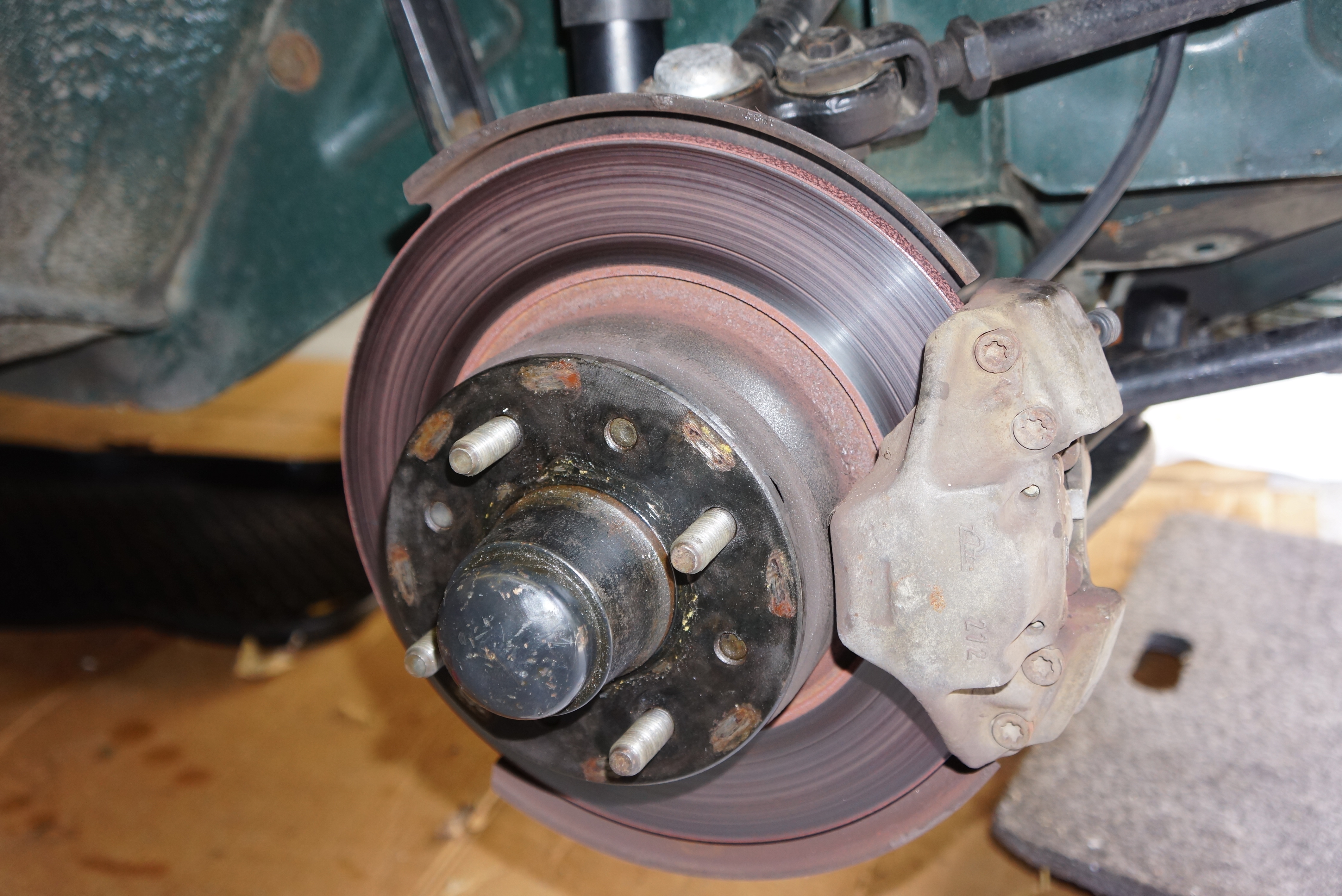
Once Geo got the car back to his place, the smoke returned, only this time, the source was clear: it was pouring off the right front brake. Hindsight made the drifting and low power obvious: this brake caliper was seized. I was lucky we weren’t seeing flames.
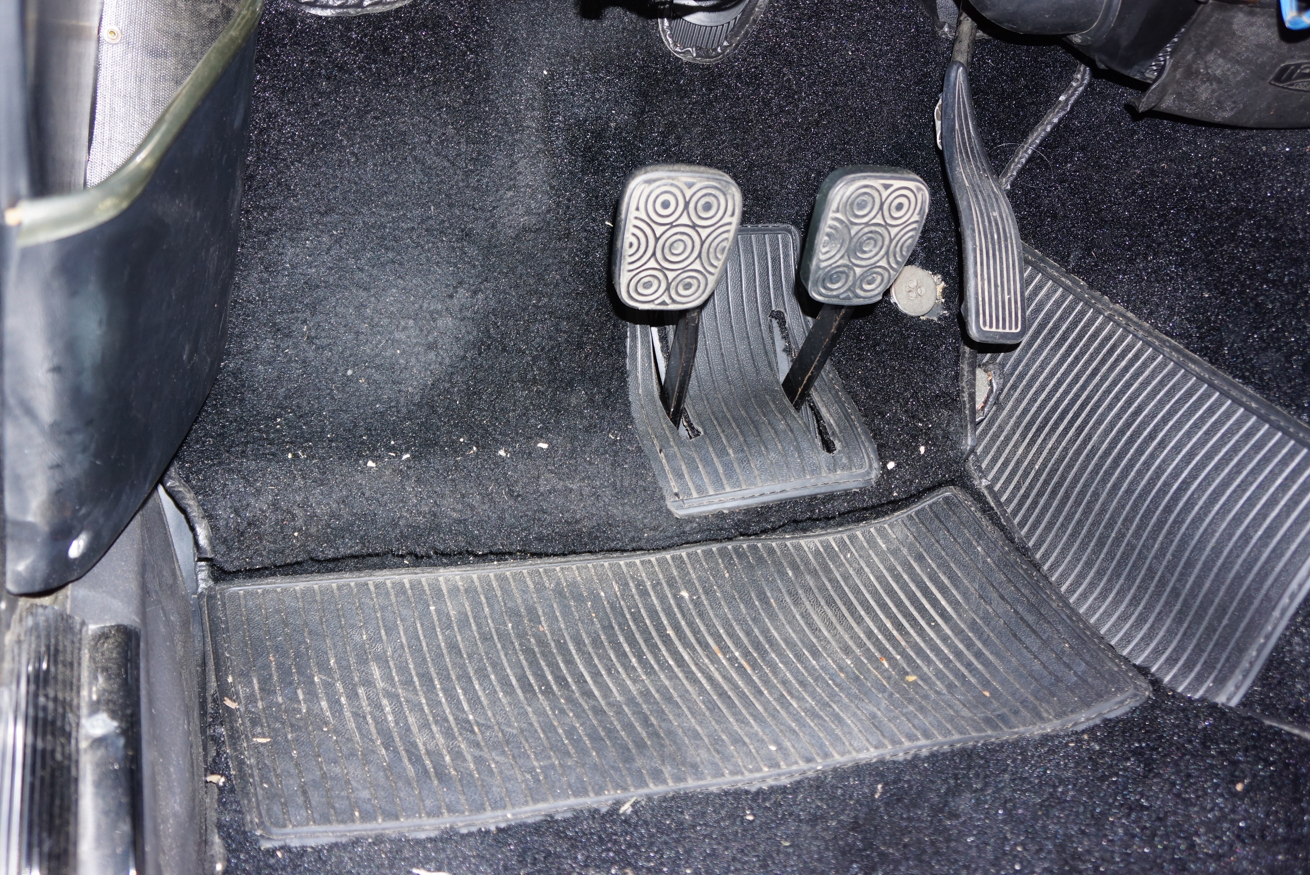
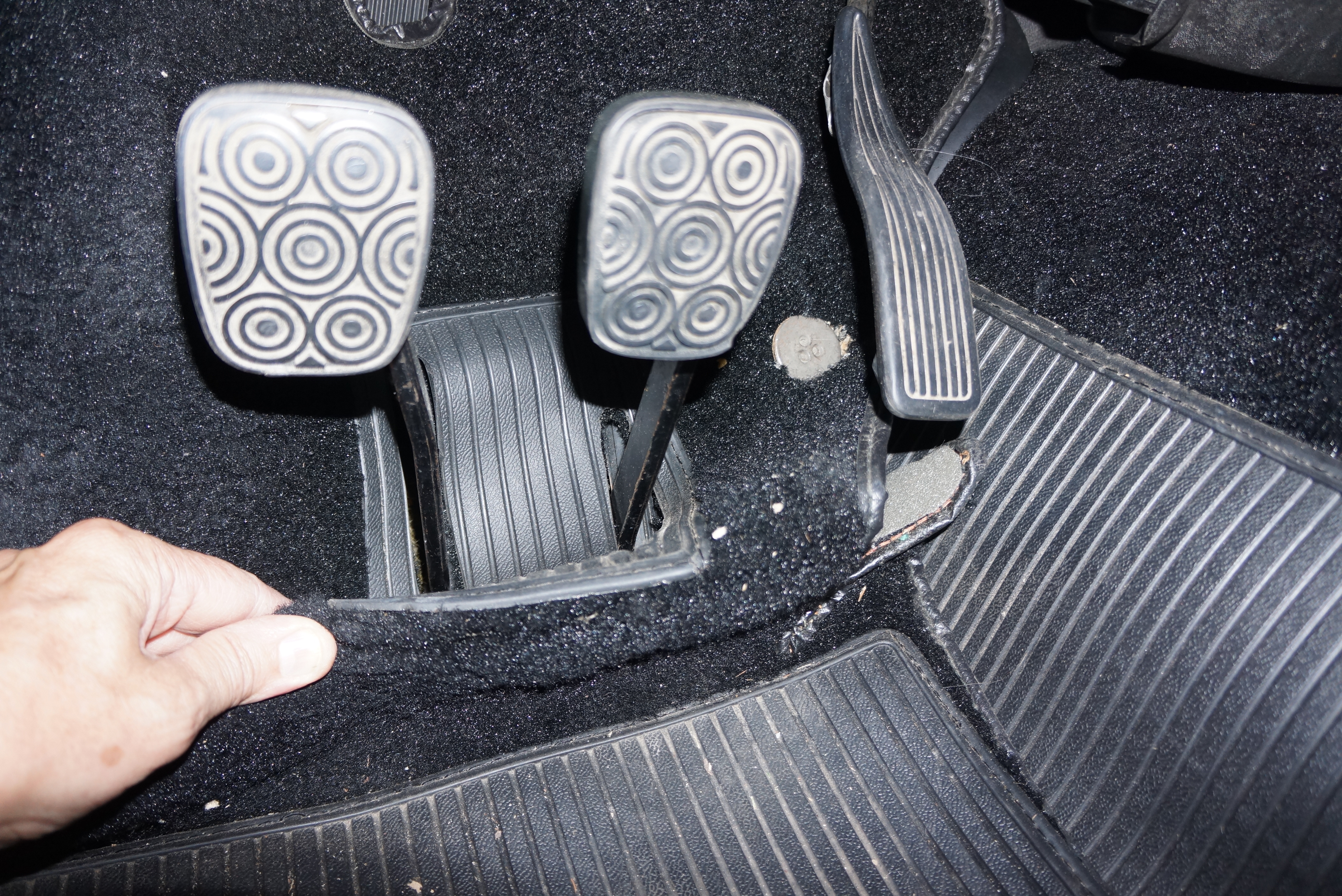
We pulled the wheel and there was nothing visibly wrong that we could try to fix on the spot. Putting the wheel back on, I reasoned that I could “carefully” drive the 5 miles back home, and work on it there. As soon as I bade Geo ciao, I started the car, put it in first, and headed down his driveway to the street, where I would need to turn left. Hitting the brake pedal, it sank to the floor. Thankfully, my parking brake (sort of) works, and I used it to stop at the bottom of the driveway. I backed the car up the drive, and started to figure out what Plan B looked like.
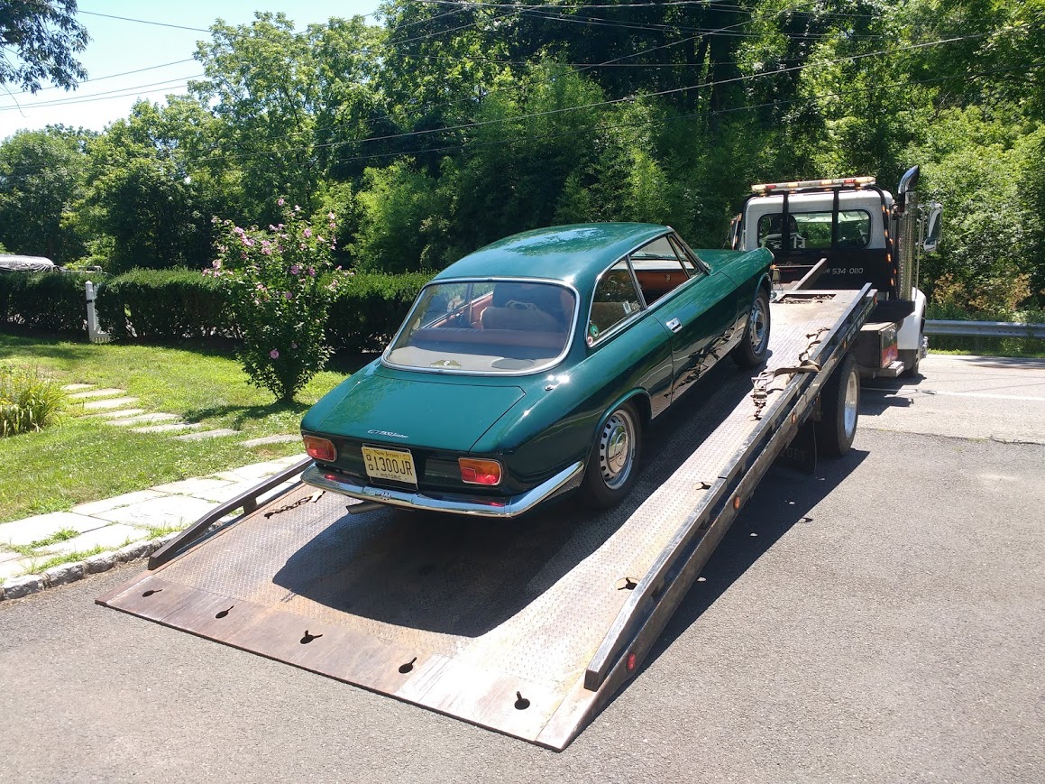
Geo couldn’t understand the loss of the pedal. I reasoned that the heat had caused the fluid to boil. Sure enough, 15 minutes later, a firm pedal returned. But I wasn’t driving this car home. There’s a reason I carry an AAA card. I called, they said one hour, and the truck was there in 90 minutes. In seven seasons of ownership, and in over 11,000 miles of driving, this car has never ridden on the back of a flat bed – until this brake failure. But the risk in driving it wasn’t worth it.
While waiting for the truck, I had time to calculate how I was going to get this repaired by Friday morning, just a few hours shy of four days away. My go-to Alfa parts supplier, Classic Alfa in the UK, was still open, if barely. I had always placed my orders via their website, never by phone, and this seemed like a most valid reason to spend the money for an international call. Given their stellar shipping reputation, I could have the parts by Wednesday, which I reckoned would still allow enough time to make a repair.
I called. ‘Chris’ answered. I explained my dilemma and asked him about my options. He quickly offered the choice of either remanufactured (reman) ATE calipers, or brand new ones. I asked him for the price difference, and he replied about 20 British pounds (approximately $25 thanks to the Brexit-depressed value of the pound). I figured that the small differential between new and reman made the new ones a deal, so I ordered a set. Since a core return wasn’t required, I asked Chris to include a caliper rebuild kit, thinking that I would eventually refurbish the old ones. It was now close to noon on Monday in New Jersey, and Chris said I should see the parts by late Wednesday.
Chris was wrong. The parts were in my hands at 5:30 pm ON TUESDAY. This was a miracle, and I presumed that the boys in the UK pushed the order through, having heard that I was planning on driving this thing to the U.S. Alfa convention in 4 days. So far, so good.
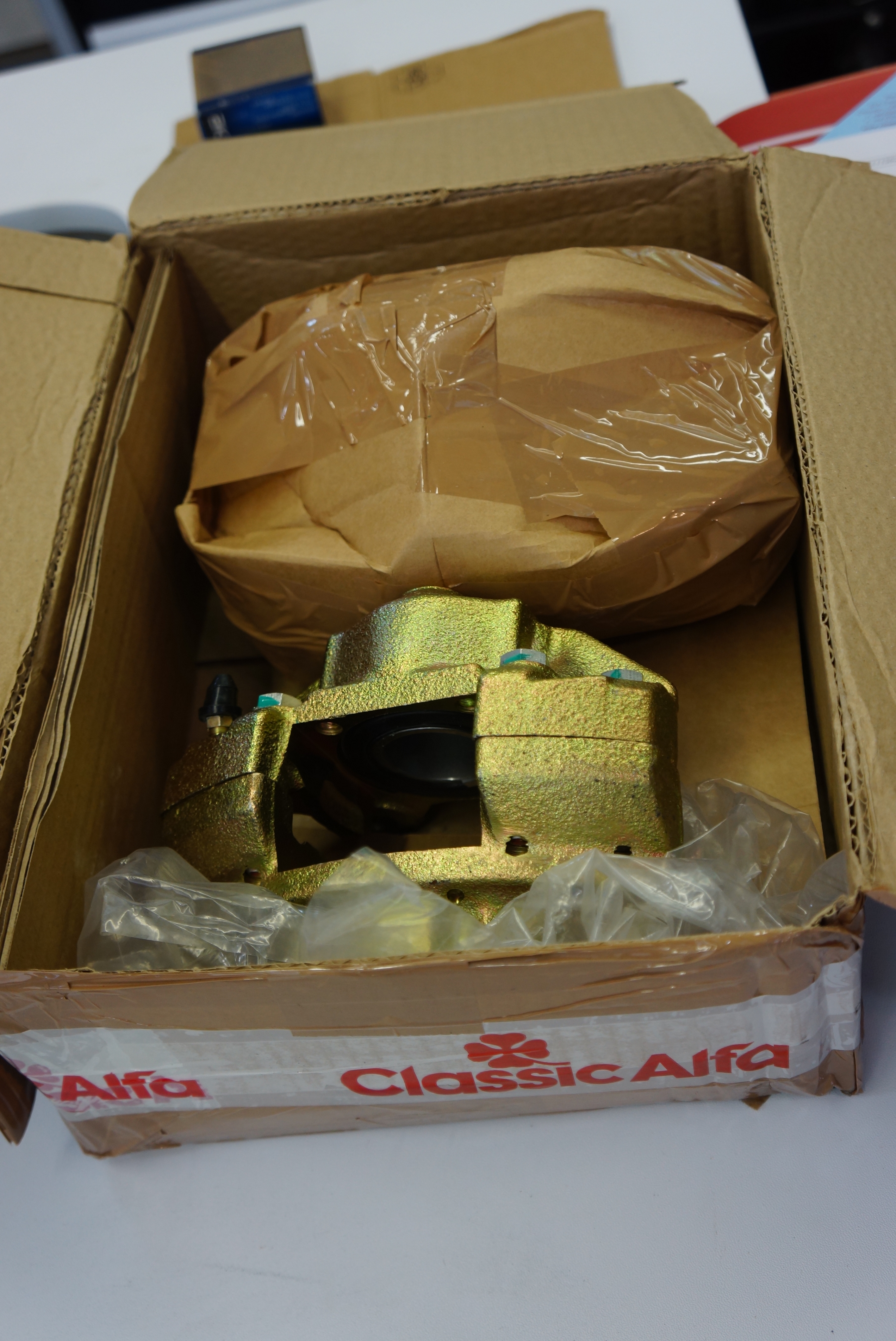
Opening the box, the first disappointment was to discover that while these were certainly new calipers, they were not marked ATE, and I had to conclude that they were ATE copies. I unbolted the offending caliper, and an eyeball comparison proved that the new one was identically shaped. All I had to do was swap over the pads, connect the hard brake line, and bleed the system.
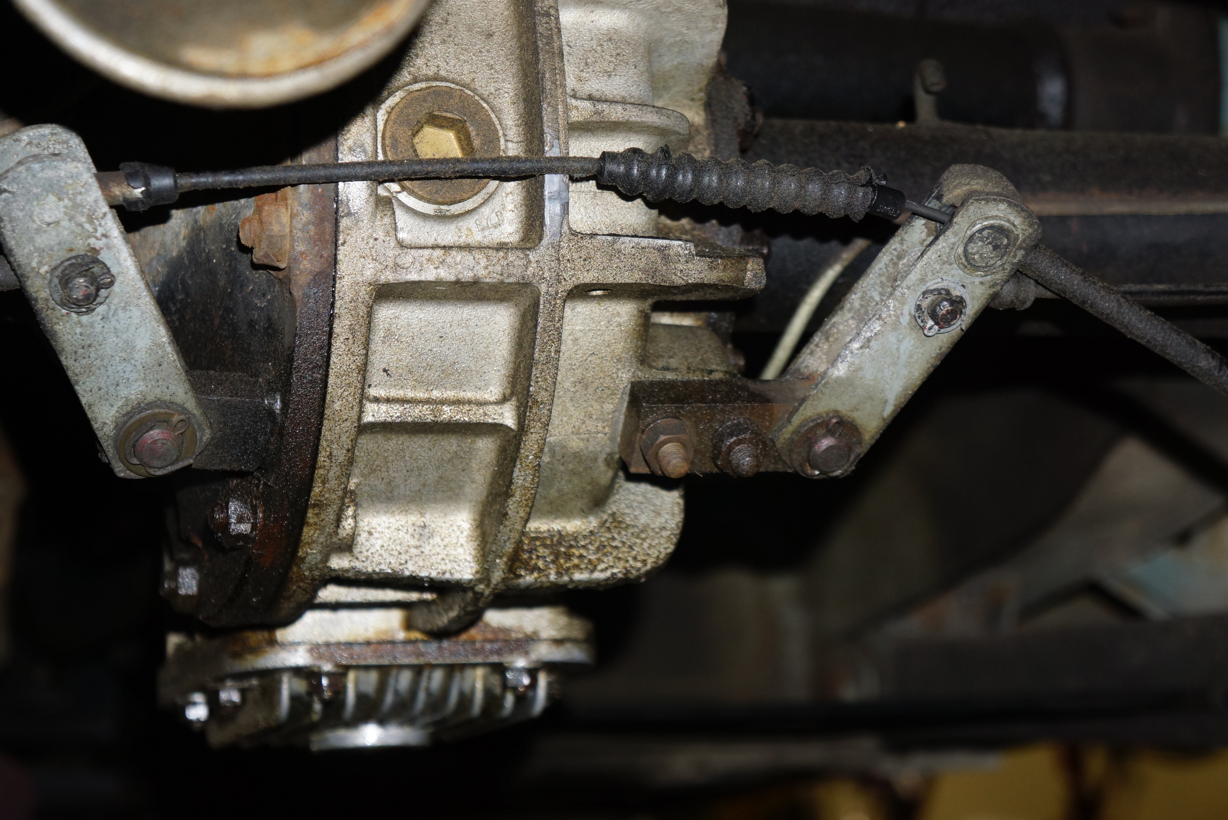
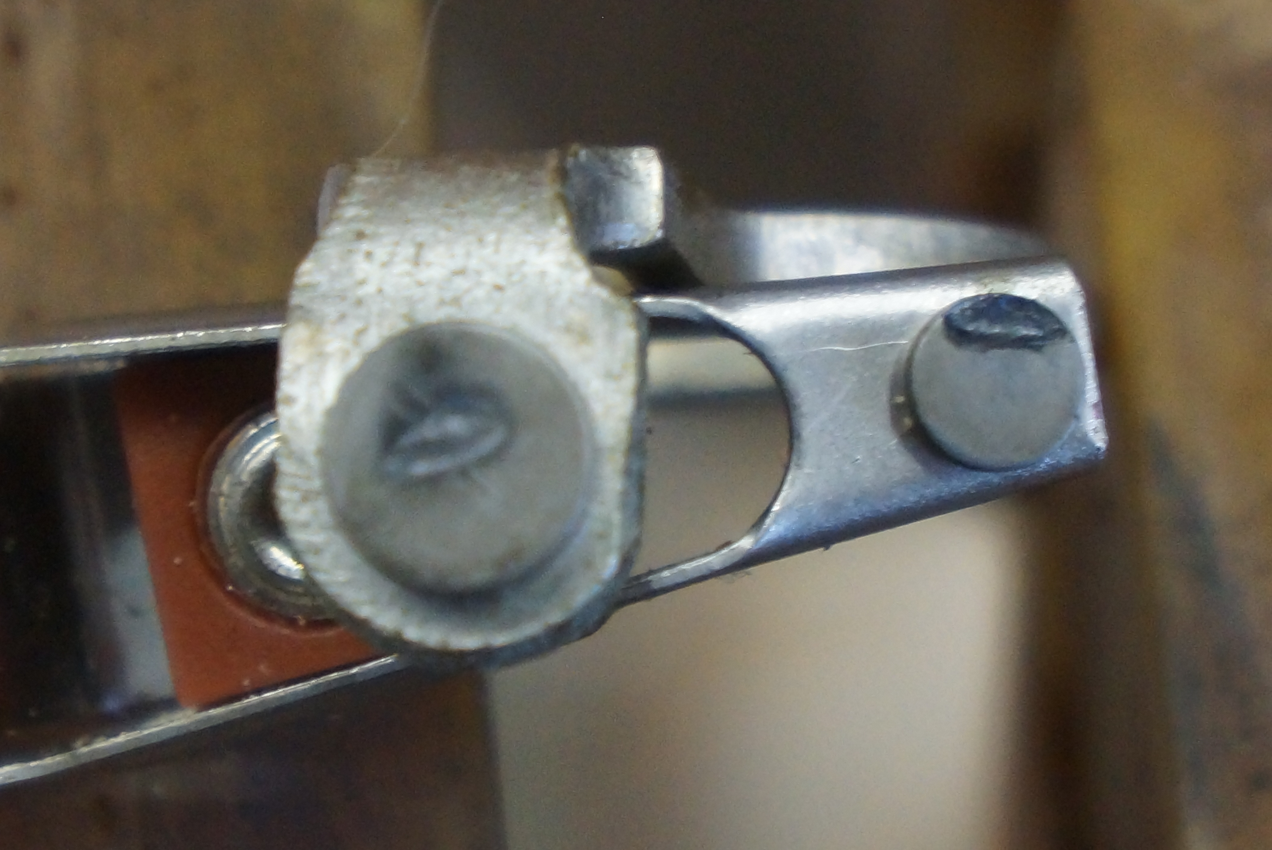
With the existing pads and pad hardware installed, I knelt at the right front knuckle, held the 11 pound caliper in my right hand, and began to thread the brake line fitting into the new caliper with my left hand. The threads would not start. I tried every trick I knew; after perhaps 20 minutes, it felt like the threads had started, but I was unable to turn the fitting by hand more than half a turn. Of course, the dreaded fear is that I might cross-thread it, and ruin the caliper and/or the brake line fitting. After another 20 minutes, with blisters forming on the pads of my fingers, it felt again like it started. I picked up the flare nut wrench, and slowly, carefully, brought the fitting all the way down. It was about 8pm on Tuesday night. I was drenched, from both the 100% humidity and the nervous energy.

The next evening, I removed the (good) left front caliper, and, convinced that the previous night’s issues were behind me, went through the same routine: swapped the pads, held the caliper up to the knuckle, and began to thread the pipe fitting. SAME PROBLEM. Desperate, I removed the hard line from the car, and brought it and the new caliper to the workbench, where I wouldn’t need to struggle with the caliper’s weight. I never came close to getting the threads to start.

I rationalized: I have the new caliper on the right front, to replace the known bad caliper. Certainly, I can keep the existing left front caliper in place and drive the car a few hundred miles. The left front caliper was reinstalled. Geo stopped by to assist. We were ready to bleed (the brakes, not us). I filled the master reservoir, asked Geo to climb in, and we began the “pump, hold, release” routine of manual brake bleeding.
There was a drip at the fitting at the right front caliper.
Reluctantly, I put a wrench on it and got another 10-15 degrees in clockwise motion. The bleeding resumed, and so did the dripping. I told Geo that we were done. While I did have the rebuild kit, it was now after dark on Wednesday, and I was out of time, patience, and confidence. Working on a car under such duress only encourages poor decision-making, unnecessary shortcuts, and botched repairs. My only desire was to enjoy the AROC convention, knowing that I would resume this wrenching at an unhurried pace upon my return. The new calipers would go back to Classic Alfa as defective or unusable.
… to be continued …
All photographs copyright © 2019 Richard A. Reina. Photos may not be copied or reproduced without express written permission.