There is a well-known adage that says, “If it ain’t broke, don’t fix it.” It is something that should be heeded by us car guys and gals. Among Alfa Romeo owners, there is a corollary adage which applies to Weber carburetors: “If the car runs well, don’t mess with the carbs.” Webers are unlike most other carburetors such as those found on American vehicles. After an initial set-up as found in a service manual, the choice of needle and jet sizes for Webers is made on a basis of trial and error. I believe that it was Pat Braden, the late, great Alfa guru, who advised against trying to “tune” your Weber carburetors without checking other engine basics first.
I bring this up because for the thirteen years I’ve had my GT 1300 Junior, during which I’ve driven it over 14,000 miles, the engine has always run strongly. One issue, though, has been that the spark plugs quickly turn black, apparently from an overly rich fuel mixture. (The engine uses almost no oil; at most, a half-quart in between oil changes.) Rather than try to “adjust” my dual Weber carburetors, I replace the plugs. Spark plugs are less than five dollars each, and the set of four takes about twenty minutes to replace. As a rule, I have been swapping out spark plugs once a year at the start of the driving season.
Last year, when I changed the plugs (which have exclusively been NGK B7ES), I moved up to the next hottest heat range plug, the B6ES. In 2024 I put about 1,100 miles on the Alfa, and there was no perceptible performance difference with the hotter plug. However, when I pulled the plugs a few weeks ago to check them, I was impressed. To my eye, there was less build-up on the plug tips, to the point where I decided to leave the plugs in place. The one-step-hotter plugs did a better job of burning off deposits, without affecting drivability.
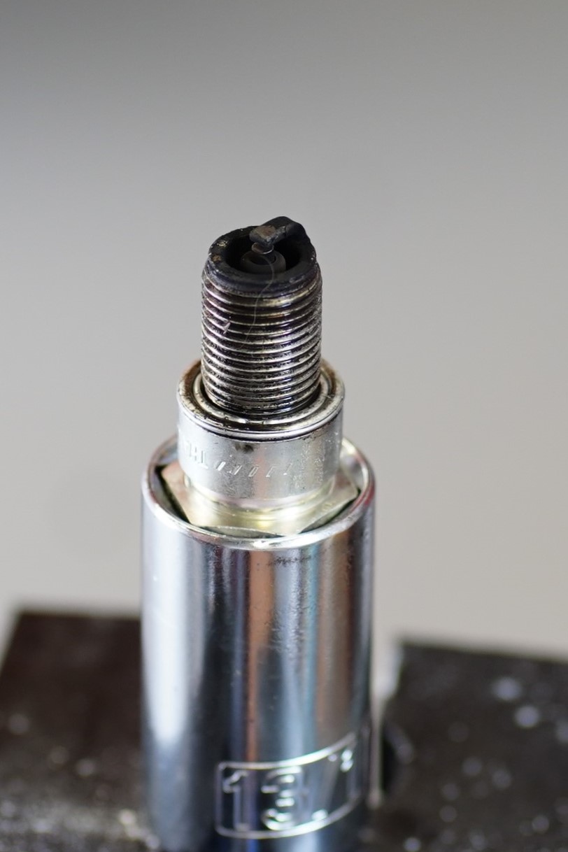
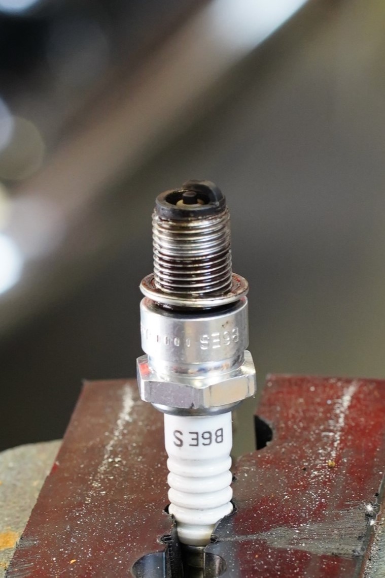
This was not easy to capture in photographs, but take a look at the two pictures and see if you can tell that the B6ES plug looks cleaner than the B7ES plug. I have two spare sets of the B6ES plugs, so if need be, I can quickly replace the set. But for now, I will leave them in the car and see how it goes. I’m expecting to possibly get a complete second driving season from them.
The “colder” plug, the NGK B7ES, shows some heavy deposits.
The “hotter” plug, the NGK B6ES, looks serviceable still after one driving season.
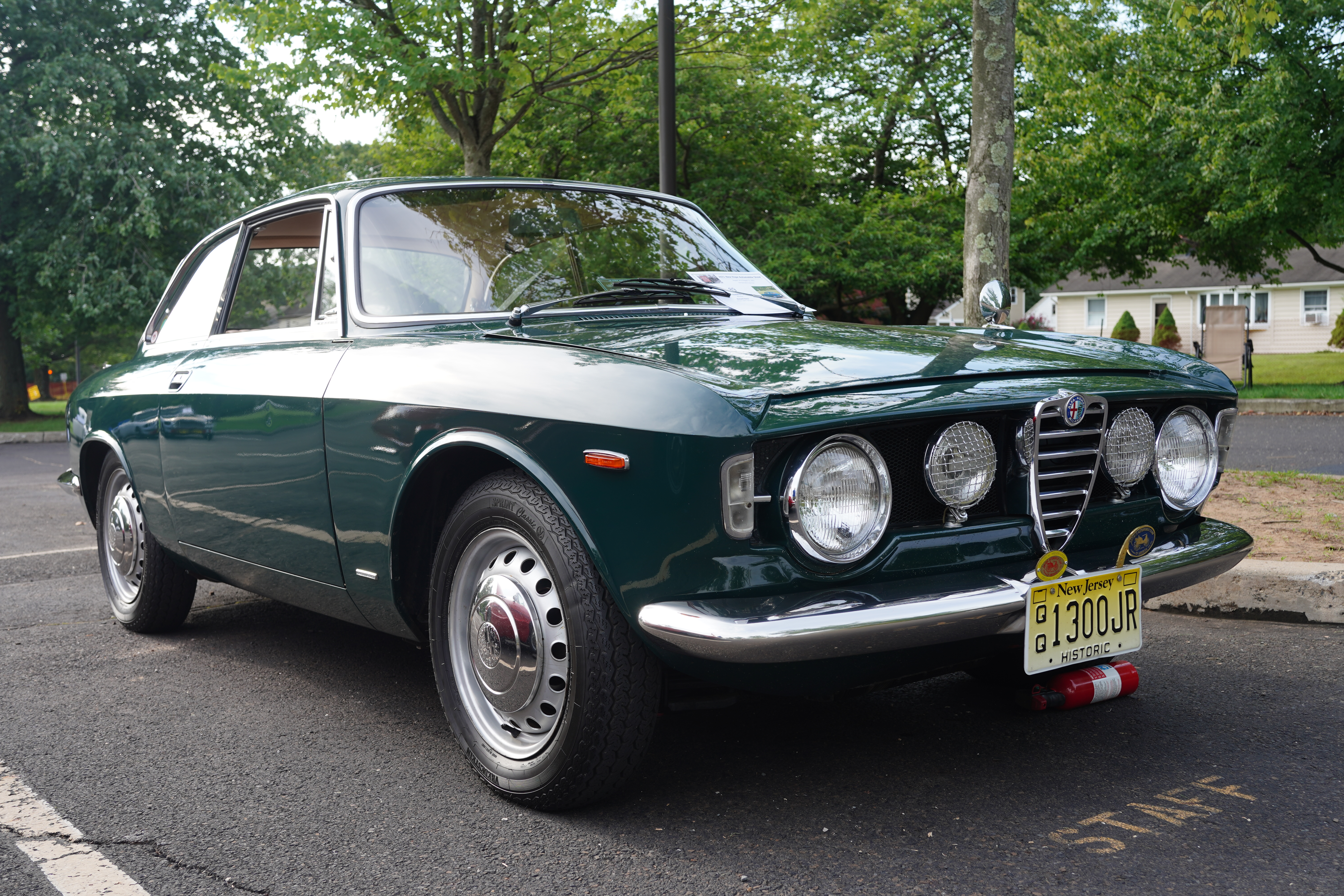
When I bought my ’67 Alfa Romeo GT 1300 Jr. from my friend Pete in 2013, it was already wearing its HPOF badge from the Antique Automobile Club of America (AACA). Pete had prepared the car for judging and was solely responsible for taking the car through the certification process. (We must also remember that he owned the car for 45 years, preserving it in its outstanding condition all that time.) Although I’ve been very involved in AACA activities over the last 2 decades, including showing both the BMW Isetta and the Mazda Miata at Hershey, up until now I had never entered the Alfa in an AACA National Show. It’s been in NJ Regional shows, but National judging is stricter.
The Saratoga Springs National which was held last week seemed to be the ideal place to enter the car for continued HPOF certification. I spent many hours during the spring detailing the car as well as attending to its maintenance needs to ensure a confident and reliable 400+-mile round trip. As you may have read in my most recent post, the car performed flawlessly in getting me there and back. Now, here’s the rest of the story.
HPOF, which stands for Historical Preservation of Original Features, is a judging class which rewards originality. Cars in this class are not restored. In fact, a car which has been restored would be deemed ineligible. Once a vehicle is certified HPOF, it is eligible for the next level of certification which is “HPOF Original”. The difference is in the number of allowable points which can be deducted. Put simply, an “HPOF” car may have X number of non-original components and still be certified, while an “HPOF Original” car will need to have a fewer number of non-original components.
Owners are required to complete a sheet, indicating exactly what on the car is not original. That sheet is then handed to the judging team. For me, I noted that the front fog lights, replacement alternator (generator was factory original), battery relocation from engine compartment to trunk, and added ammeter gauge were the non-original items. The judges only spent a few minutes examining the cars (the steady showers kept them moving quickly from car to car), and at the Saturday banquet, I was honored to be presented with an HPOF Original badge for the Alfa! I admit I got a bit emotional because my mind went back to my friend Pete, who passed away last October. He would have been thrilled to know this, and as I told my fellow hobbyists at the dinner table, Pete gets most of the credit for this achievement.
ABOVE: The HPOF badge on the left was awarded to Pete, probably around 2003. The “AACA Original” badge on the right was given to me last week, and mounts behind the existing HPOF badge.
HPOF cars are always eligible to the shown at subsequent National meets, where they will either continue to be certified at their current level of achievement, or have the certification reduced or removed. For example, if I were to repaint my Alfa and replace its 1300 cc original engine with a larger and more powerful Alfa engine, I would completely lose its HPOF rating. (And of course I have no intention of doing anything of the sort.) The plan, both short-term and long-term, is to keep driving the car, keep up its maintenance, and keep it as original as it is today!
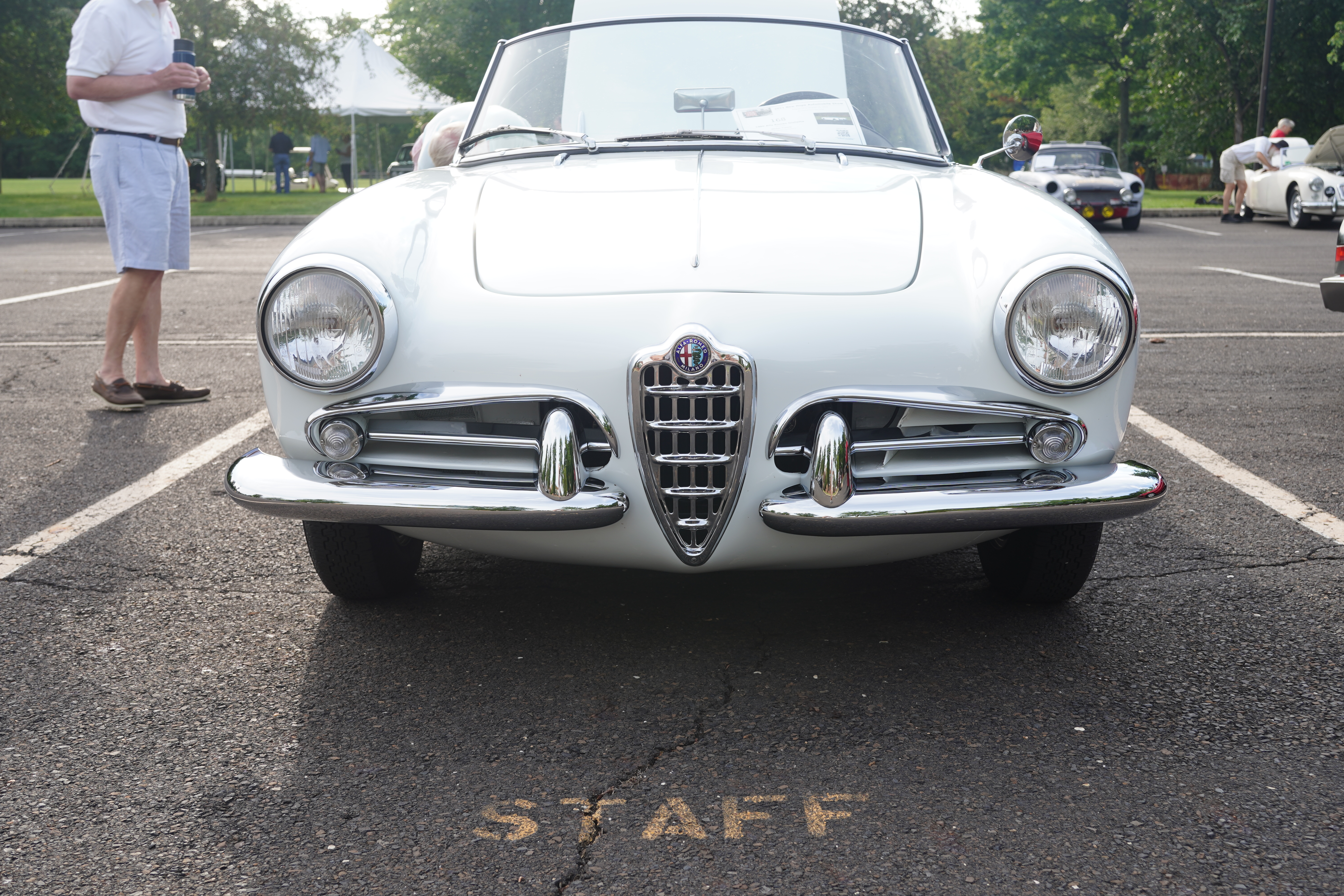
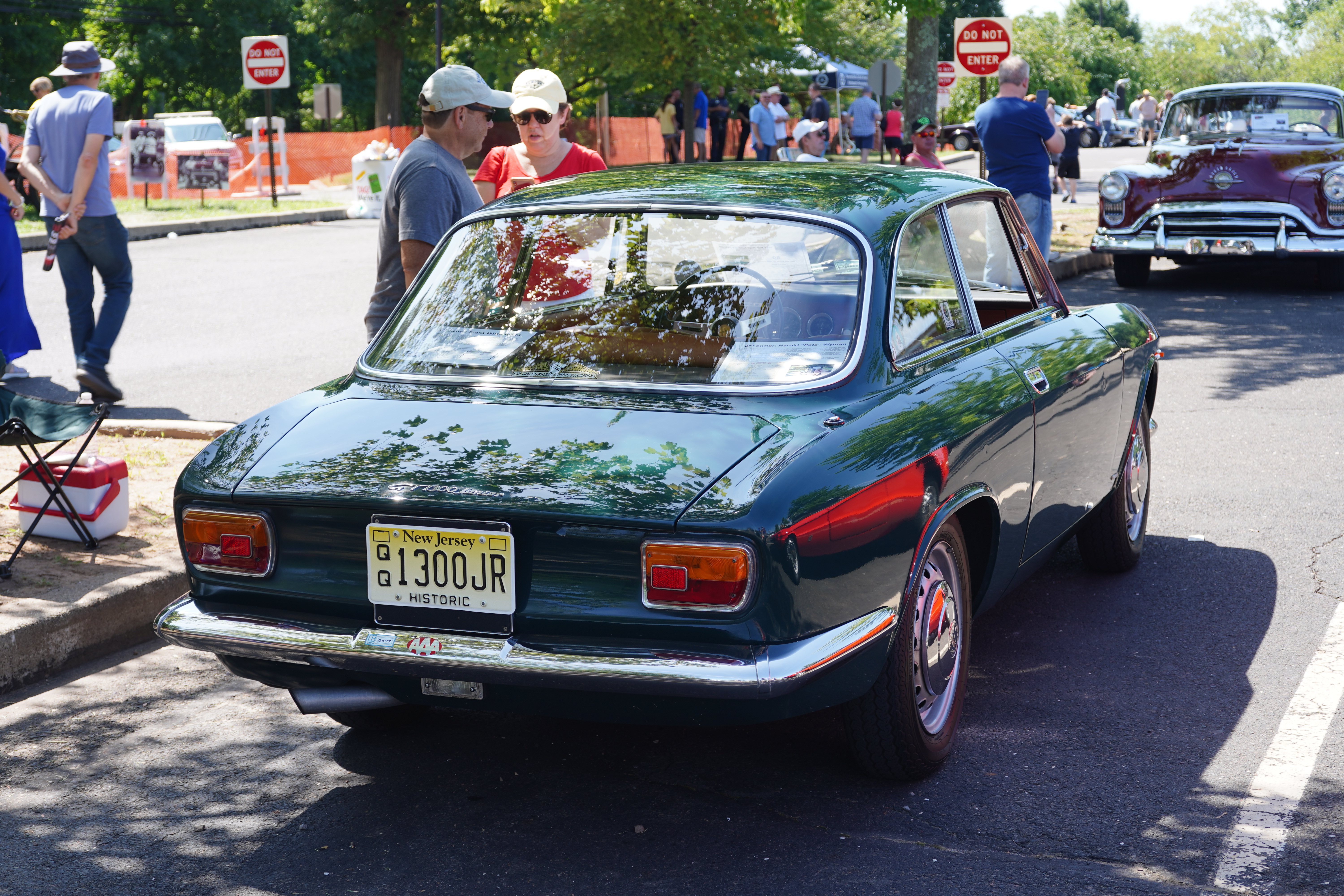
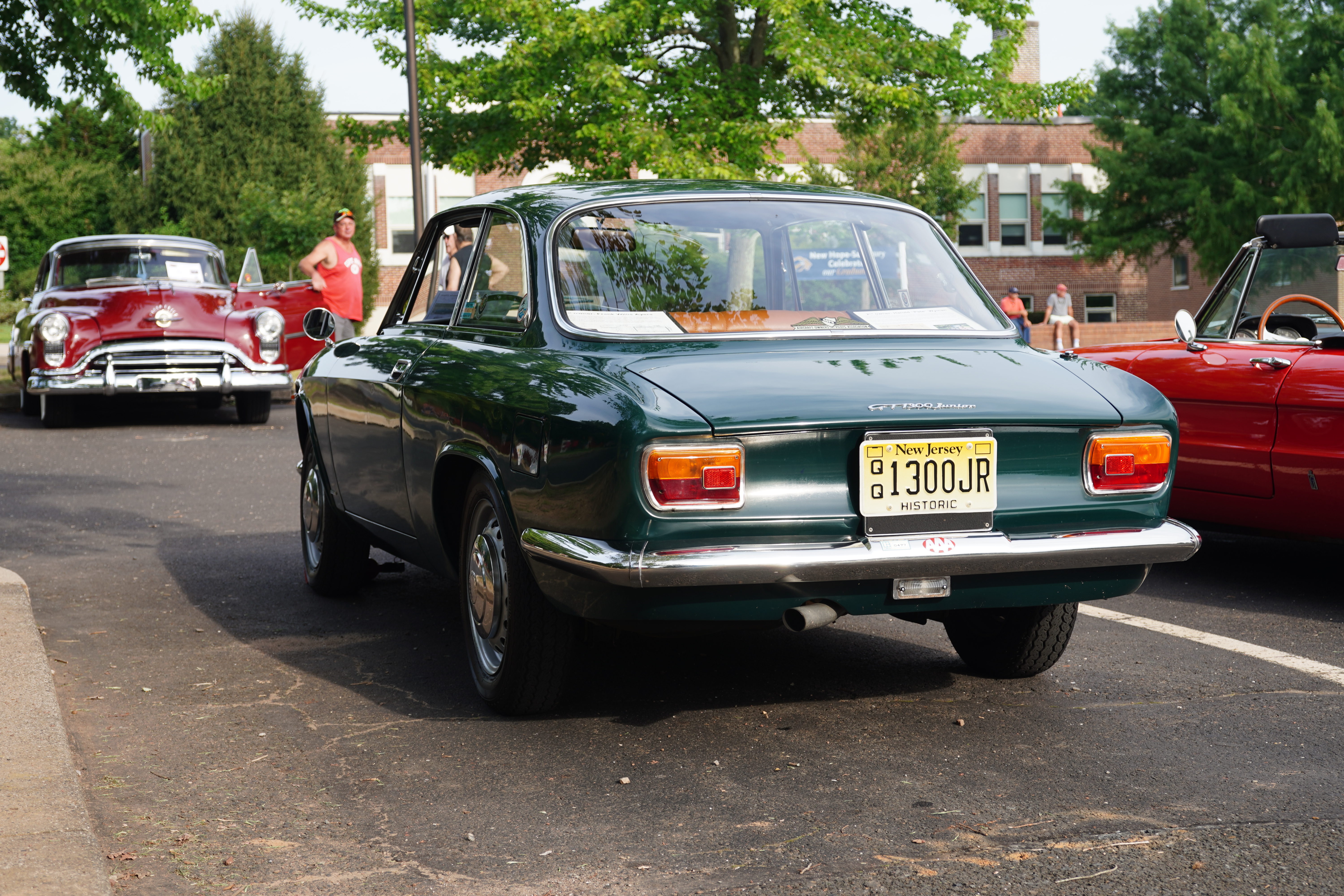
The 2021 New Hope (PA) Auto Show was held during the weekend of August 14-15. This is one of the longest-running car shows in the Northeast, and this year’s arrangement split participants into two groups: the domestic cars on Saturday, and the import vehicles on Sunday. My Alfa was registered for the Sunday event, and, expecting a significant turnout of Alfas buoyed by support from both the NJ and Delaware Valley Club Chapters, I was not disappointed.
The weather cooperated; Sunday was one of the nicer days we’ve had during what’s been a hot and humid season. Registrants were asked to arrive by 8am; I was five minutes early and gained a coveted shady spot at the start of the row dedicated to Alfa Romeos. Within a few minutes, another dozen or so Alfas arrived; I later counted over 20 of the cars from Milano.
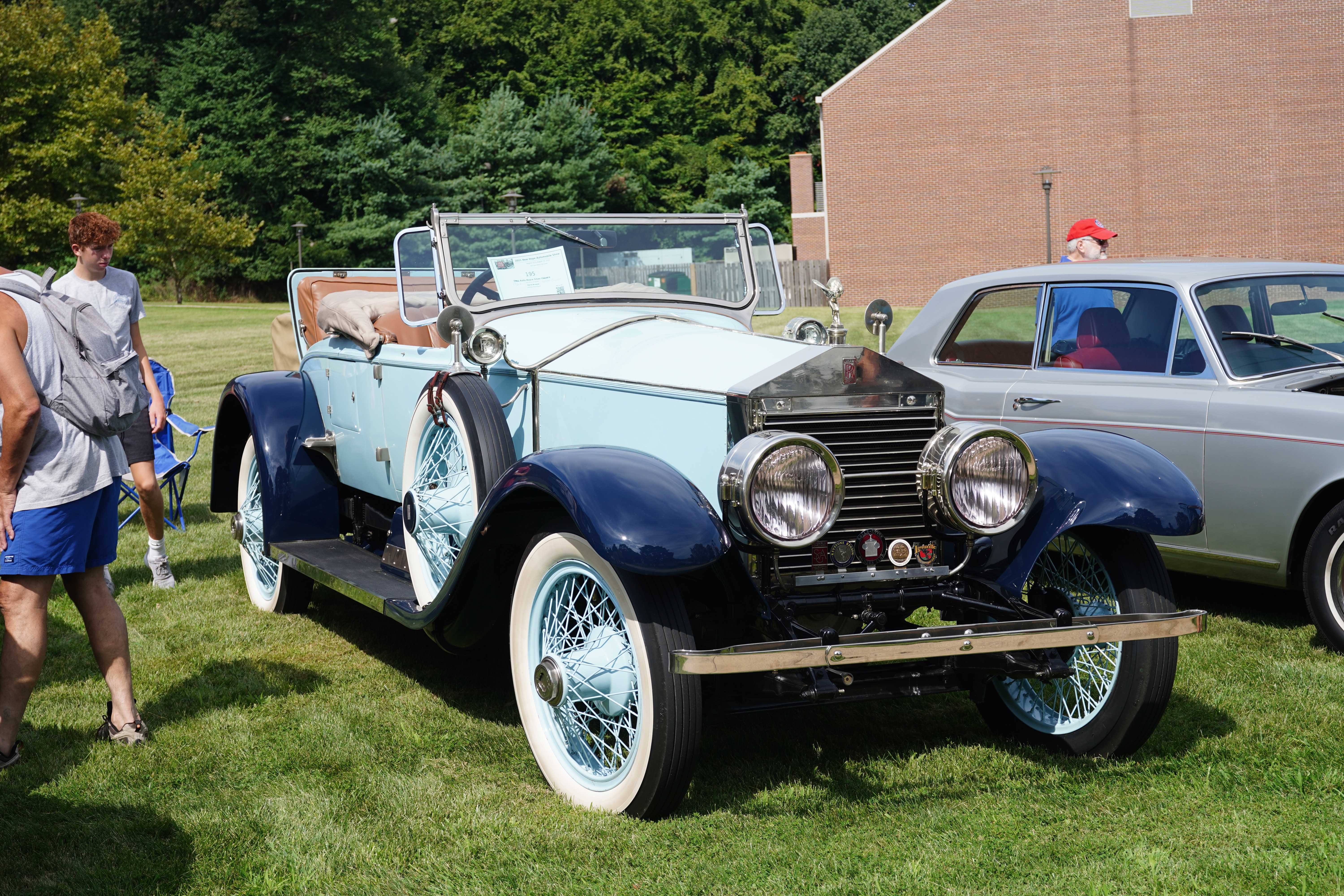
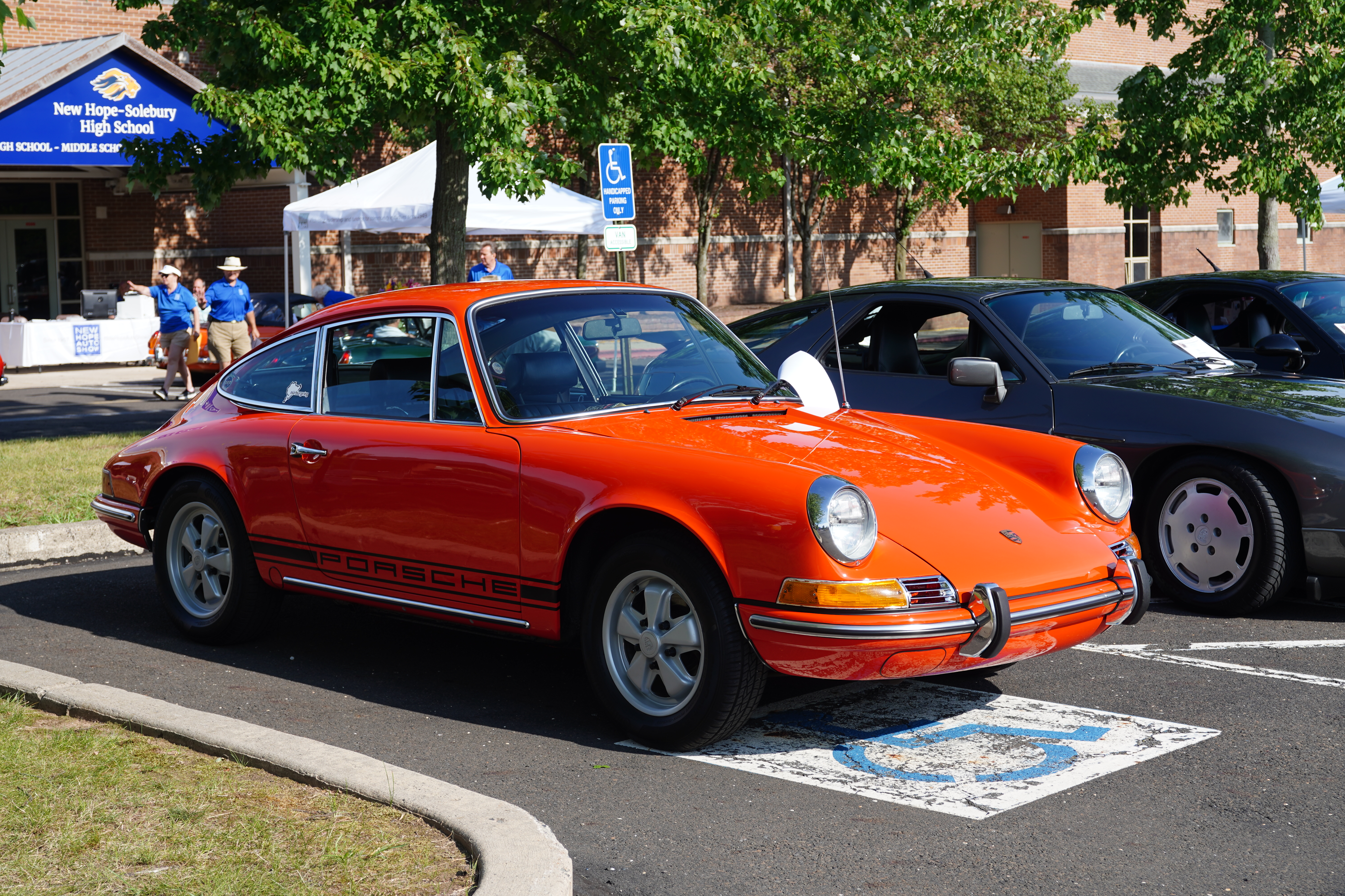
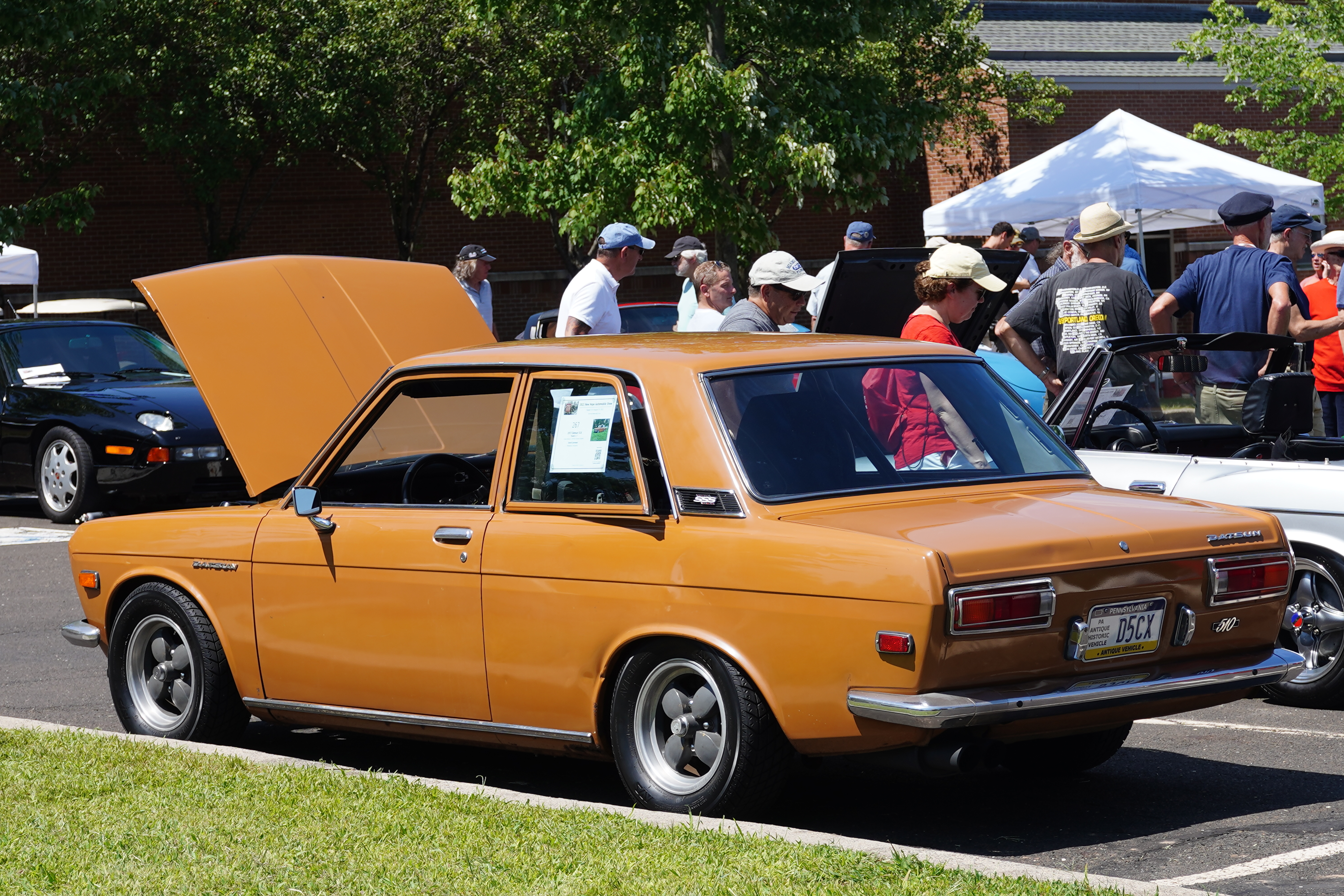
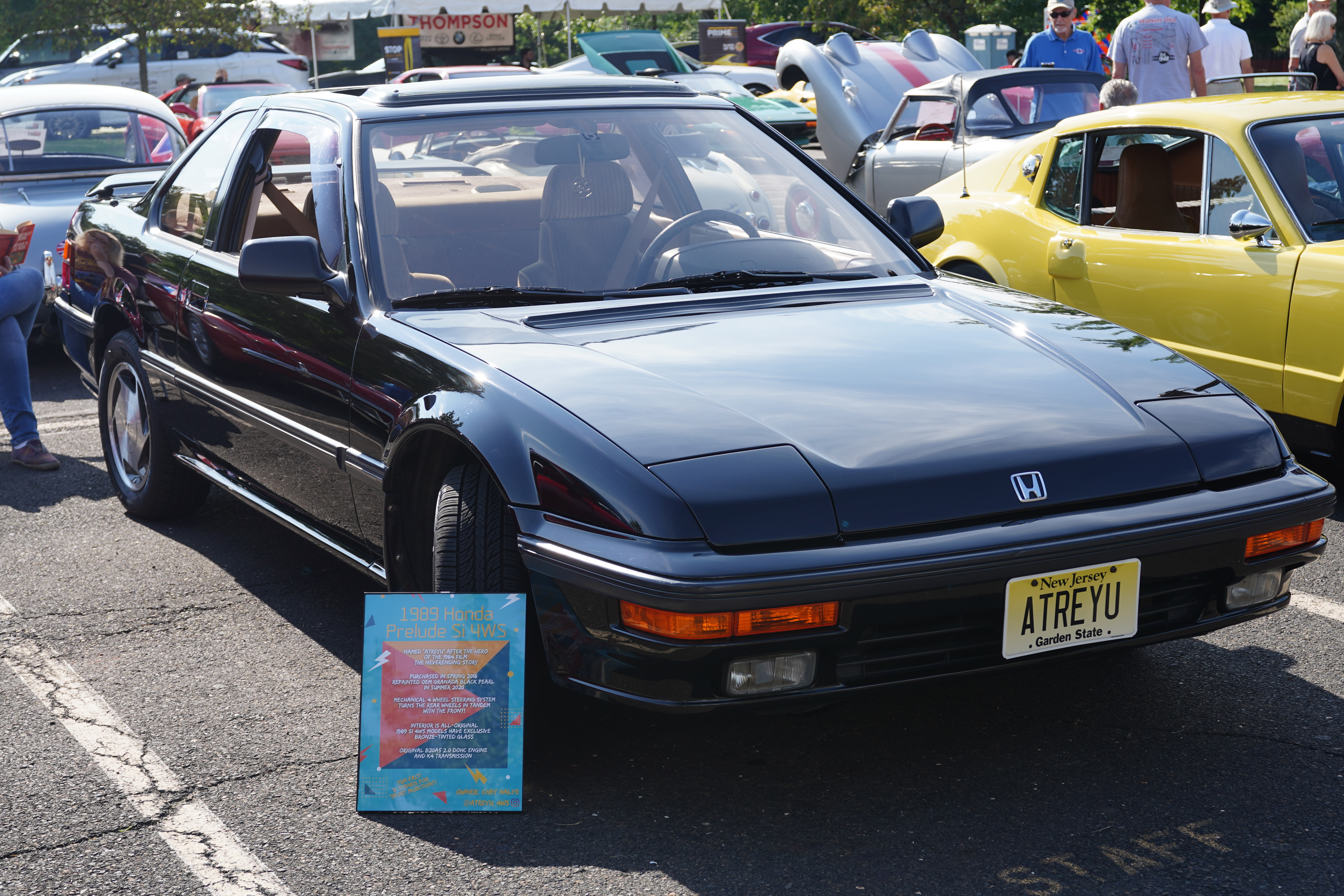
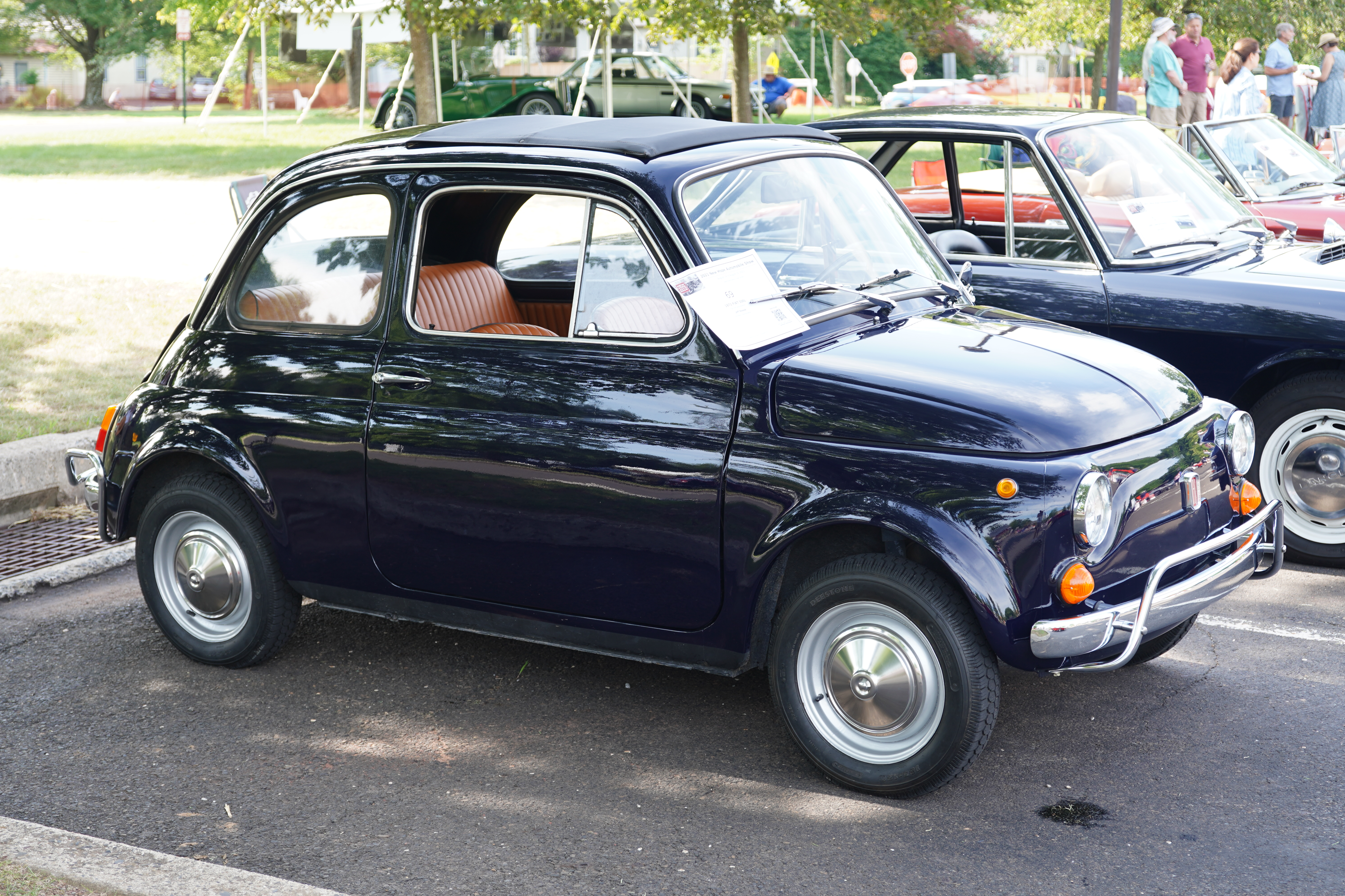
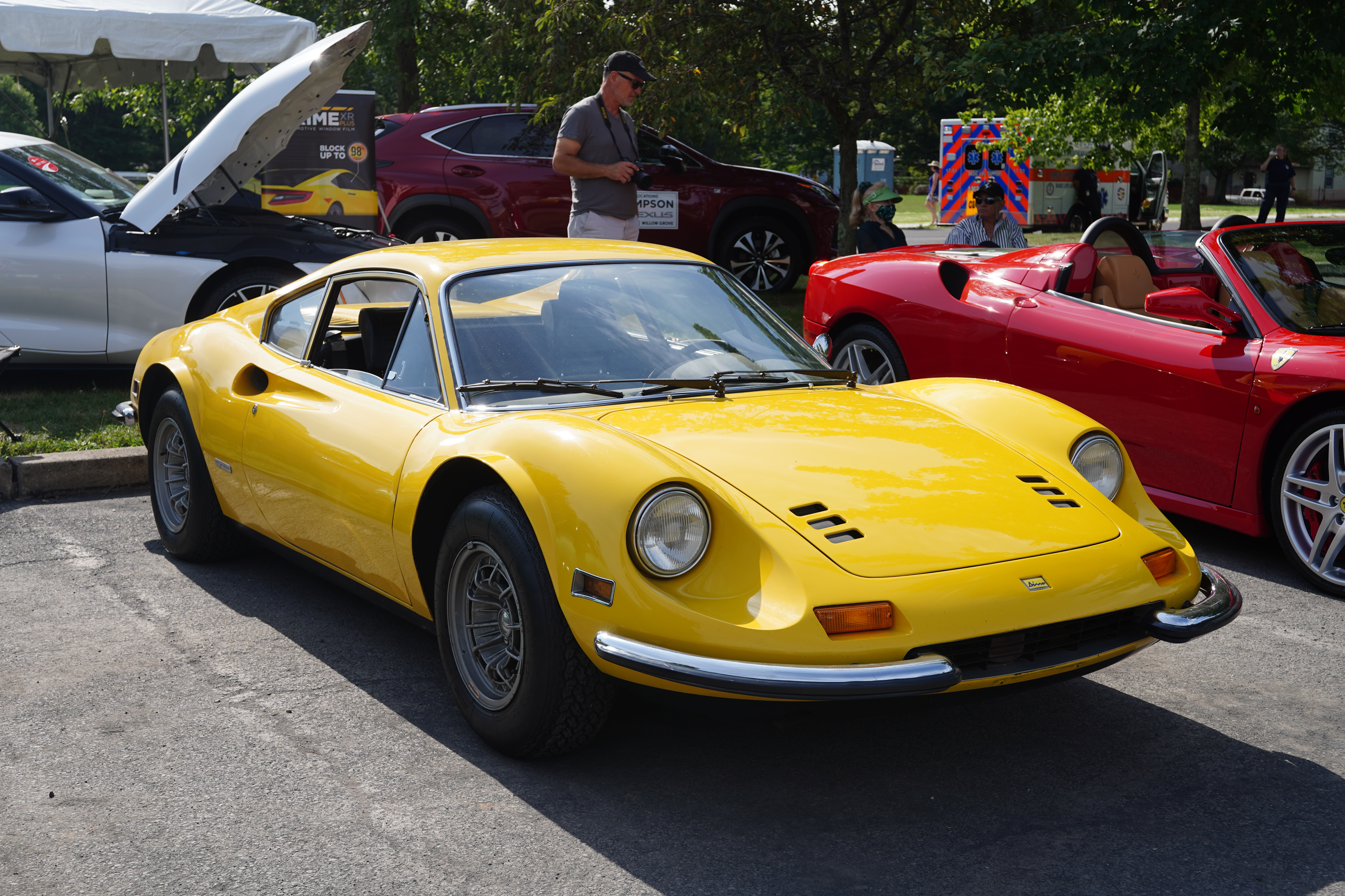
Of course, other marques were also amply represented: Porsches and BMWs from Germany; Jaguars and MGs from the UK; other Italian cars including Fiat, Lancia, and Ferrari; and Asian brands including Honda, Mazda, and Datsun/Nissan. It is worth mentioning that the Rolls Royce/Bentley Club had what was likely the largest turnout of vehicles of any particular make.
One change for 2021 was the lack of formal judging; the stated reason was that Covid concerns prevented the show organizers from gathering judges to perform their needed tasks. Instead, spectators were encouraged to vote for their favorites, and ribbons were presented around 2pm, after which the show cars were released from their spots.
This was the first time my Alfa had ventured out-of-state since I drove it to a NY diner during a Sunday breakfast run in April of 2019. While New Hope is barely 30 minutes from me, it still was a great feeling to venture that far from home in confidence after the significant brake and carburetor overhauls.
With the Alfa’s hydraulic brake replacement essentially finished, there was one more related task to complete. As the previous owner had suggested to me, the battery B+ cable could stand to be replaced. Not only had he indicated that it was undersized, he also wasn’t sure that its attachment points had stood up over time. (My car was born with its battery in the engine compartment, but Pete had relocated it to the trunk, where it still is.)
Conveniently, the cable almost completely followed the routing of the brake line from rear to front. There was no extra work to dropping the battery cable when removing the brake lines. The old cable looked to be possibly 2 gauge; I had purchased a “Battery Relocation Kit” which included 20 feet of zero gauge cable (the smaller the number, the larger the cross-section). I only needed about 16 feet.
The old cable had been secured in place with metal hose clamps; thankfully, there were no signs of potential incendiary damage. The new cable followed the same routing as the old, and instead of clamps, I used about two dozen high-temp plastic cable ties. (Cable, or “zip” ties, are available in different quality levels. In the past, I had some which snapped upon tightening. For this job, I researched and purchased higher quality cables.) I was quite happy with the appearance of the end result; the new cable is tucked far enough up into the underside that at no point is it the lowest object under the car.
New battery cable securely in place under the car
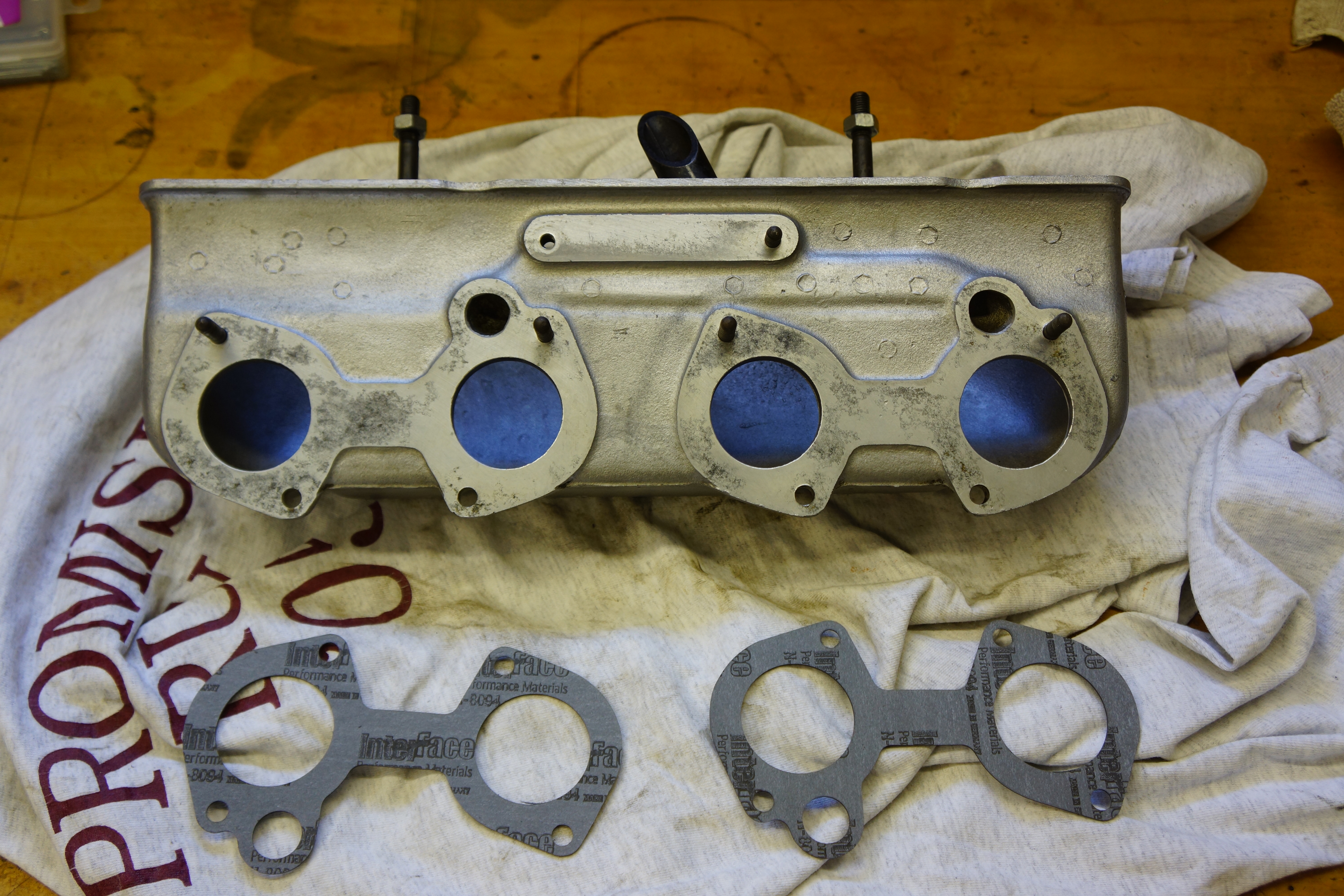
To gain access to the starter solenoid, I had removed the intake plenum. (Alfas and some other Italian cars do not have a traditional intake manifold. Instead, the air filter feeds air to the plenum, mounted to the outside of the side-draft carburetors. The carbs in turn are mounted to small tubes which themselves are bolted directly to the cylinder head.) I gave the plenum a cleaning, ran a 6mm x 1.0 tap on all the studs, used new washers and nuts, and with new gaskets at the ready between plenum and carbs, bolted it all back together. The thread chasing and new nuts helped immensely given that 4 of these attachments are completely blind and are in tight quarters.
Dirty plenum, old gasketsClean plenum, new gaskets
Saturday was going to be the big day; there always are the dozen final details (spark plug wires and various other small connections underhood), and I triple checked all around the car, which was still on jackstands, still with tires off. The battery had been on trickle charge. Nervously, I completed the final connections at the battery. Nothing caught fire. Climbing up into the driver’s seat, I turned the key on, pumped the pedal about a half-dozen times, and cranked. The crank was strong, but the engine made no attempt to run on its own. Key off, pump the pedal some more, try again. And again. I smelled fuel, got out, and peered underneath. Raw fuel was pouring out from under the front right corner. Key off, battery safety switch turned to off. Time to stop, take a breath, and think.
Was this related to what I had been working on the last 11 months, or was this complete coincidence? Grabbing a flashlight, I looked into the right front corner, where the mechanical fuel pump and fuel filter are. Feeling with my hands, the wettest area was the rubber fuel line for the pump’s outlet. It took about 2 minutes to loosen the clamps and remove the hose.
Old hose looks quite bad
The hose was completely dry-rotted. First, I breathed a sigh of relief that it was ‘just’ a hose. I also immediately realized that, like the brake system I had just overhauled, I really didn’t know how old these hoses were. A quick car ride (with mask) to Advance Auto Parts, and I was back with 3 feet of 5/16” fuel hose.
Old hose looks worse close up
Sunday morning, all 4 fuel hoses, each only about 8-10 inches long, came off and were replaced with fresh rubber. Time to try again. This time, after about 7 to 8 pumps of the pedal (and no leaks), the engine started. Hooray! I bolted the tires back into place, removed the jackstands, and my Alfa was back on the ground for the first time since July of last year.
New fuel hose is CARB-compliant
Gingerly, I moved the car outside under its own power. The brakes worked well, even if the pedal still felt a little soft. One more round of bleeding is in order. I’m also going to try to adjust the ‘throw’ at the master cylinder, as the brake pedal is not quite lined up with the clutch pedal. These are mere details, and I will get to them in the coming days. For now, I’m happy, satisfied, and truly pleased to be able to say that this project is done.
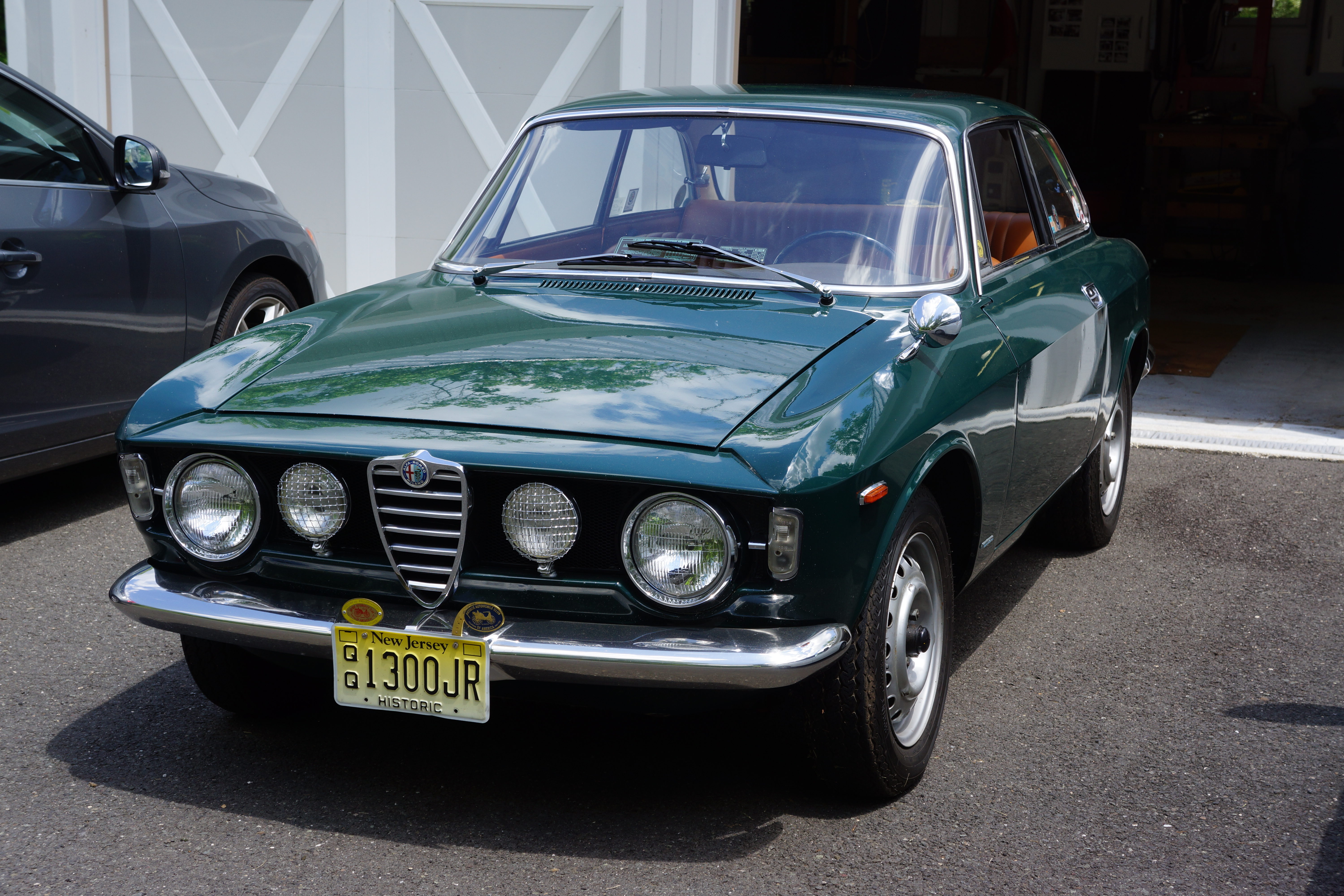
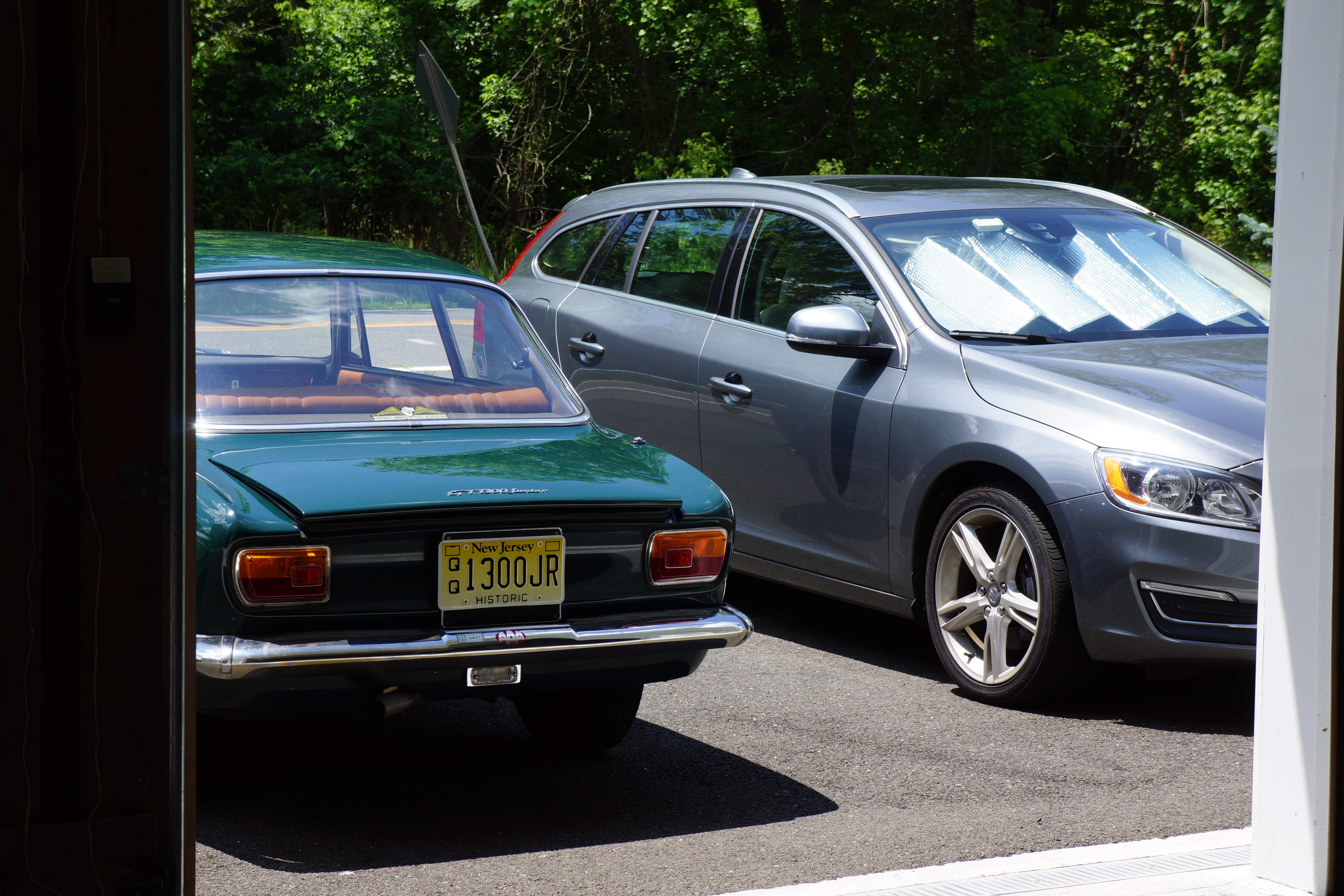
My Alfa sees sunshine for the first time in 11 months
Here, nicely framed by garage door; can’t wait to put some miles on it.
I’ve always likened working on an old car, when there’s little or nothing in the way of published instruction, to dancing the tango. It’s two steps forward, and one step back. Two forward, one back. And repeat….
In the last post about the Alfa’s brakes, two weeks ago, I wrote about the awkward position of the brake master cylinder. Like so many cars with pedals coming up from the floor (what Alfisti call “standing pedals”), the master is underneath, bolted to the pedal box. When I removed the master cylinder last fall, there were no written instructions to follow. I loosened the pedal box just enough to lower it and access the two bolts holding the master in place. The removal was such a chore that frankly I had been dreading the reinstallation.
Re-reading my words in that last post, I see that I was unintentionally vague. The sentence that now bothers me reads “Once the lines to the master cylinder are done, I need to reinstall the pedal box in the driver’s footwell, as all three pedals had to be loosened/removed to gain access to the master.” My sentence leaves it completely unclear whether I had removed the entire pedal box, or had merely loosened it, when in fact it was the latter.
Why am I harping on this? Because I found myself doing the tango. In the process of attempting to reinstall the new master, I ended up completely removing the pedal box from the car. If only I had done this during the initial disassembly! The hang-up was a bracket which I had mistakenly identified as part of the transmission cross member, but is a bracket for the front exhaust pipe. Laying on my back, on the garage floor, holding a flashlight, and trying to focus through my progressive lenses made its correct identification difficult. Once I realized that it could be safely removed, I undid 5 bolts and it was off. Suddenly, the entire pedal box was in my hands. Eureka!
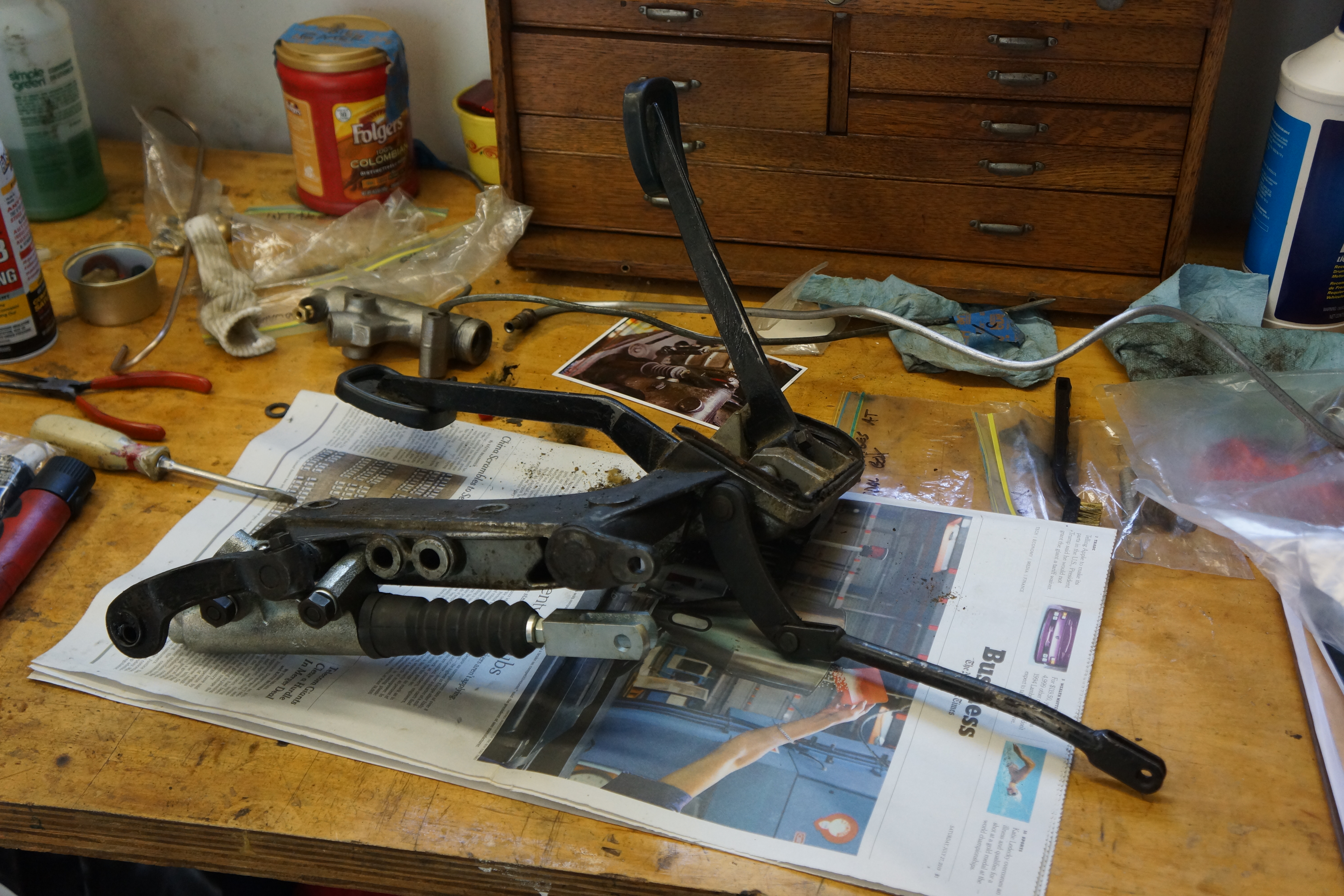
Pedal box on my workbench. New master is in front.
Since the exhaust bracket was off, I replaced the two rubber bushings inside it, cleaned it up, and repainted it with Eastwood Chassis Black. When friends ask why this brake job isn’t finished yet, it’s these “might as well as” side jobs which eat up time, but are important to complete.
Greasy exhaust bracket
Clean & ready for paint
Painted w/new bushings
Reassembled
With paint open, I dipped the bolt heads and nuts in it. Drilled wood holds them while they dry.
With the new master cylinder bolted in place, I reinstalled the pedal box, sealing it against the unibody with fresh dum-dum (I have a box of 3M dum-dum that’s probably 25 years old, and that stuff stays pliable!). The two final brake lines were bent to line up with the threaded inserts on the master, and I was happily surprised that I got the threads to “bite” after just a few minutes of trying.
Brake lines at master, ready to be bent to shape
The time had come to add fresh brake fluid to the system. I filled the reservoir, attached the little magnetic one-man bleeder bottle from Eastwood to the right rear caliper bleed screw (always start with the brake furthest from the master), and began to pump the brake pedal by hand. Forum posts on the Alfa Bulletin Board (AlfaBB) recited tales of horror about the difficulties in bleeding Alfa hydraulic brakes. I believe that later cars with dual circuits AND dual servos can be a challenge to bleed. I was happily shocked that I had fresh fluid coming through the hose on the bleeder screw on the second or third try.
This item, under $10, makes one-person bleeding a breeze
I was less happily shocked to also see that I had some leaks. There were two leaks at flare fittings that still weren’t tight enough. An eighth of a turn with the 7/16” flare nut wrench solved that. I continued to add fluid and pump the pedal, moving from right rear to left rear to right front to left front. But then a larger fluid leak sprung, from a lousy location: the master cylinder. I got under the car, but both lines at the master were as tight as I dared to make them. My heart sank. Could the new master cylinder be defective?
When you’re doing the tango, and your feet start to go in a direction that could make you trip and fall, it’s sometimes best to get off the dance floor. I put down all the tools, exited the garage, went for a walk, and came back to have lunch. (I learned during the Isetta restoration that before anxiety drives you to act hastily and BREAK something, walk away, think about it, then go back to it.)
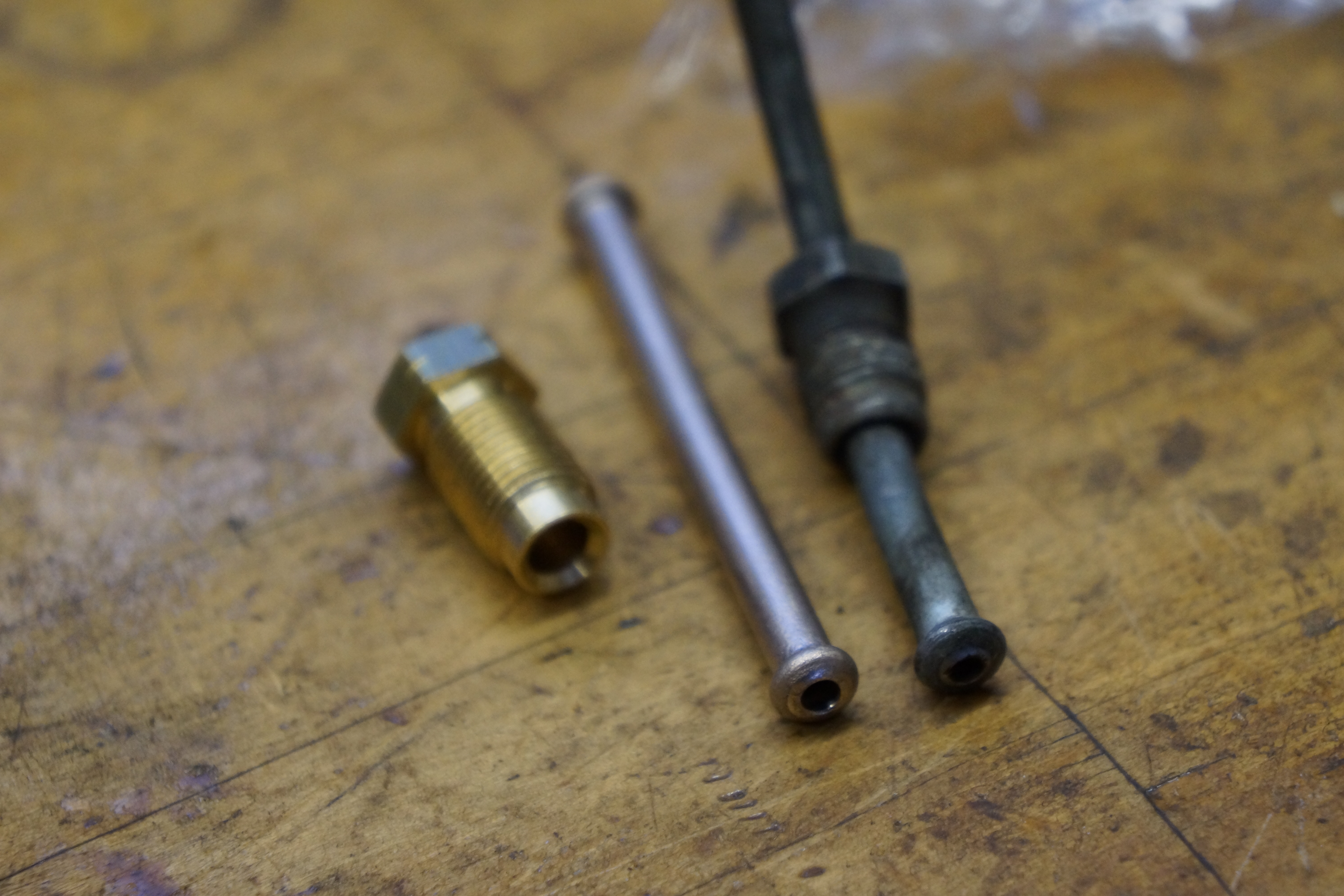
An hour later, I believed I had diagnosed the problem, without even touching the car. The leaking line ran from the exit port on the master up to the brass four-way junction block on the firewall. I remembered that when I had formed that line, I told myself that it was “symmetrical”, that is, the same flares and the same flare nuts on each end. While the flare NUTS were the same, the flare at the master needed to be an ISO bubble flare, and I had formed a 45 degree double flare. It took about two minutes to pop that line out of the master to confirm my diagnosis. Yup – I formed the wrong flare fitting.
Oops. Old line at left is bubble flare; new line with double flare doesn’t match.
Back to the two steps forward and one back routine. It was a complete pain to remove that line, cut off the wrong flare, make a new flare, and fit the line back in place. However, the rapid diagnosis made up for it. The fixed line was back on the car, bleeding resumed, and there were no leaks. In a short while, I had a pedal! I’ll bleed the entire system one more time, then the hydraulic work will be done.
Perhaps the ongoing lockdown has distorted my sense of time. Brake System Update Part 5 was posted on April 3, and I would have guessed that it was more recent than that. Progress has continued, and I’m not shy about admitting that 12 weeks of working from home has allotted additional free time with the removal of a two hour round-trip commute. It also felt redundant and nonconstructive to add a post which only stated “… and today I cut and flared two more brake lines….”
The month of May had me in limbo because of the master cylinder. I was keen on keeping the original part and simply rebuilding it. I had taken a chance last year by ordering a rebuild kit that I knew might not work, and it didn’t. Then I found a new supplier based in Germany whose website looked like they had the correct ATE rebuild kit. That order was placed in late April, and I’m still waiting. Supposedly DHL has the part (or more likely has lost the part).
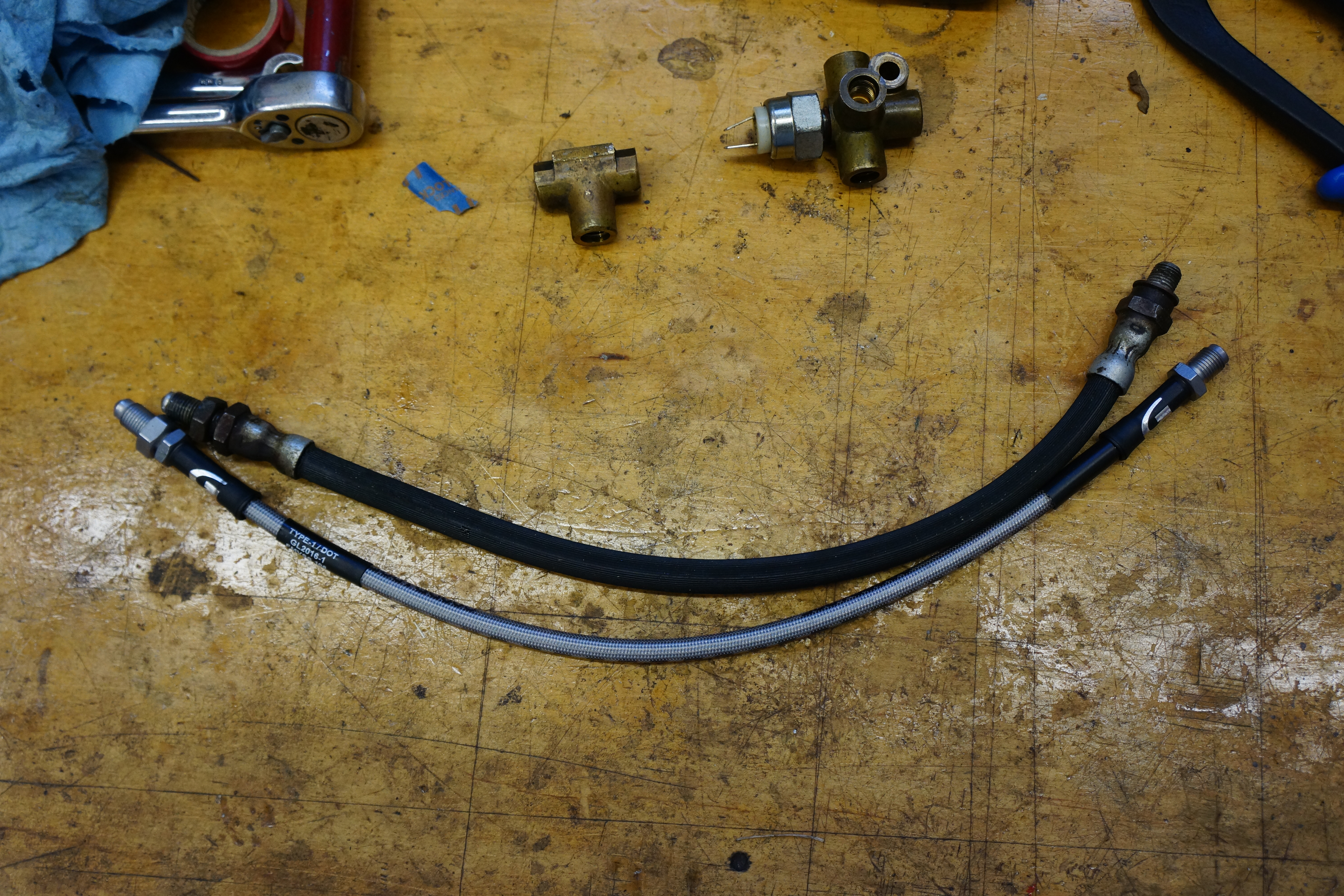
New reinforced brake hose alongside old hose
As much as I wanted to avoid the expense of a new master, I bit the bullet and bought a brand new unit (almost two bills) from my main vendor Classic Alfa. One concern is that there are so many master cylinder variants (standing vs hanging pedals, LHD vs RHD, non-servo vs one servo vs two servos, 20mm bore vs 22mm bore). While I was nervous about getting the correct one, I needn’t had worried. It arrived in two days (the usual Classic Alfa timeliness), and all threaded fittings and mounting points are 100% accurate.
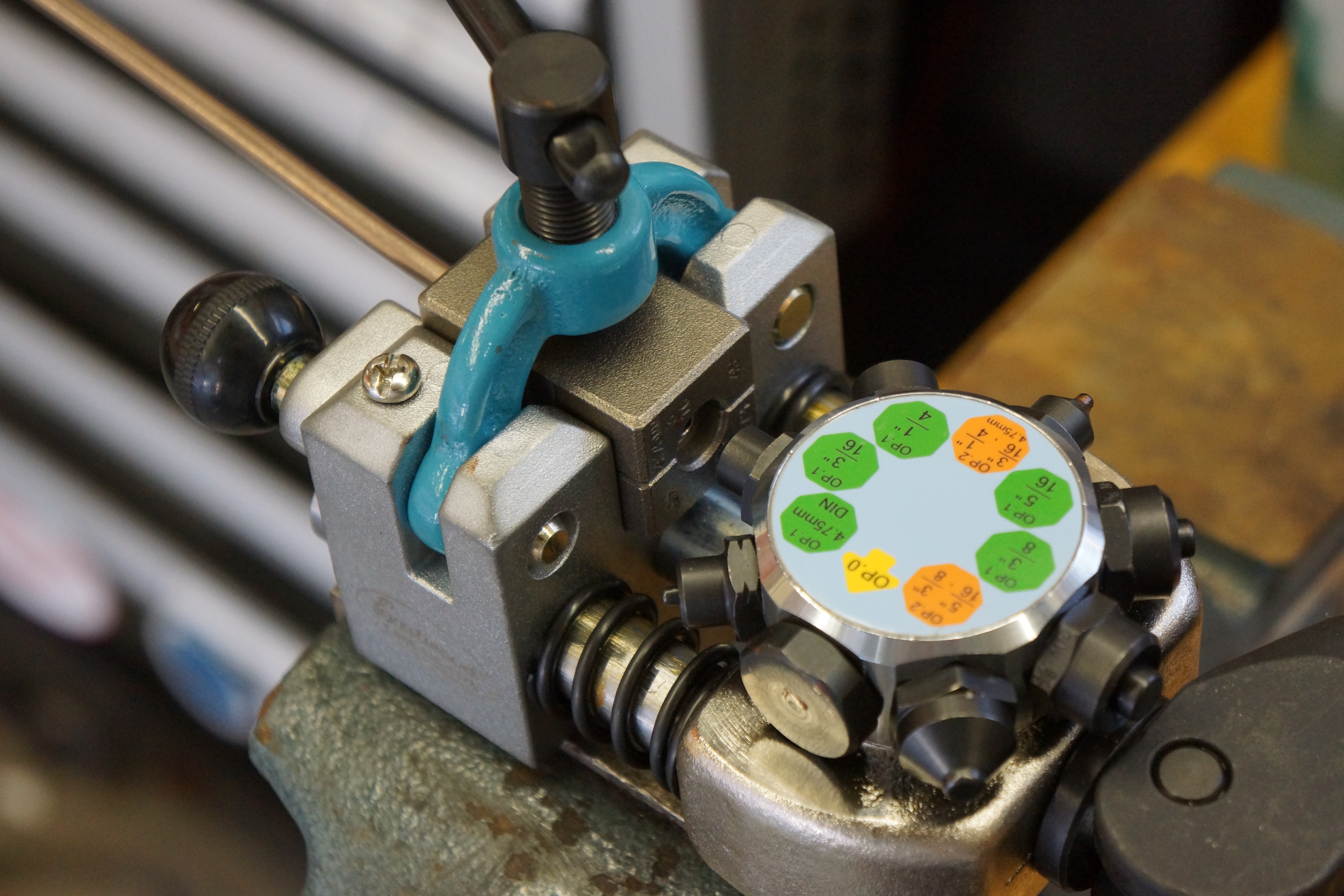
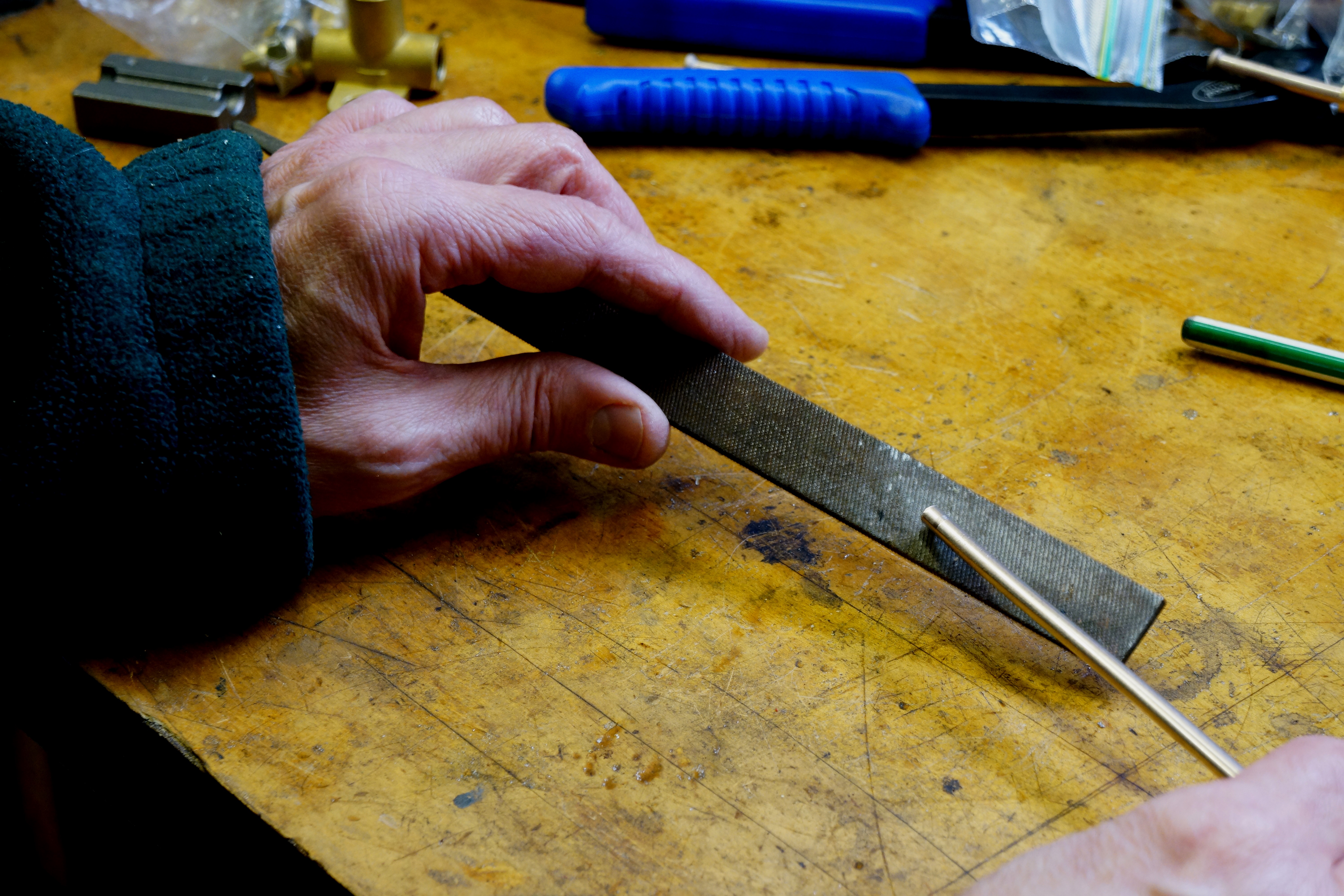
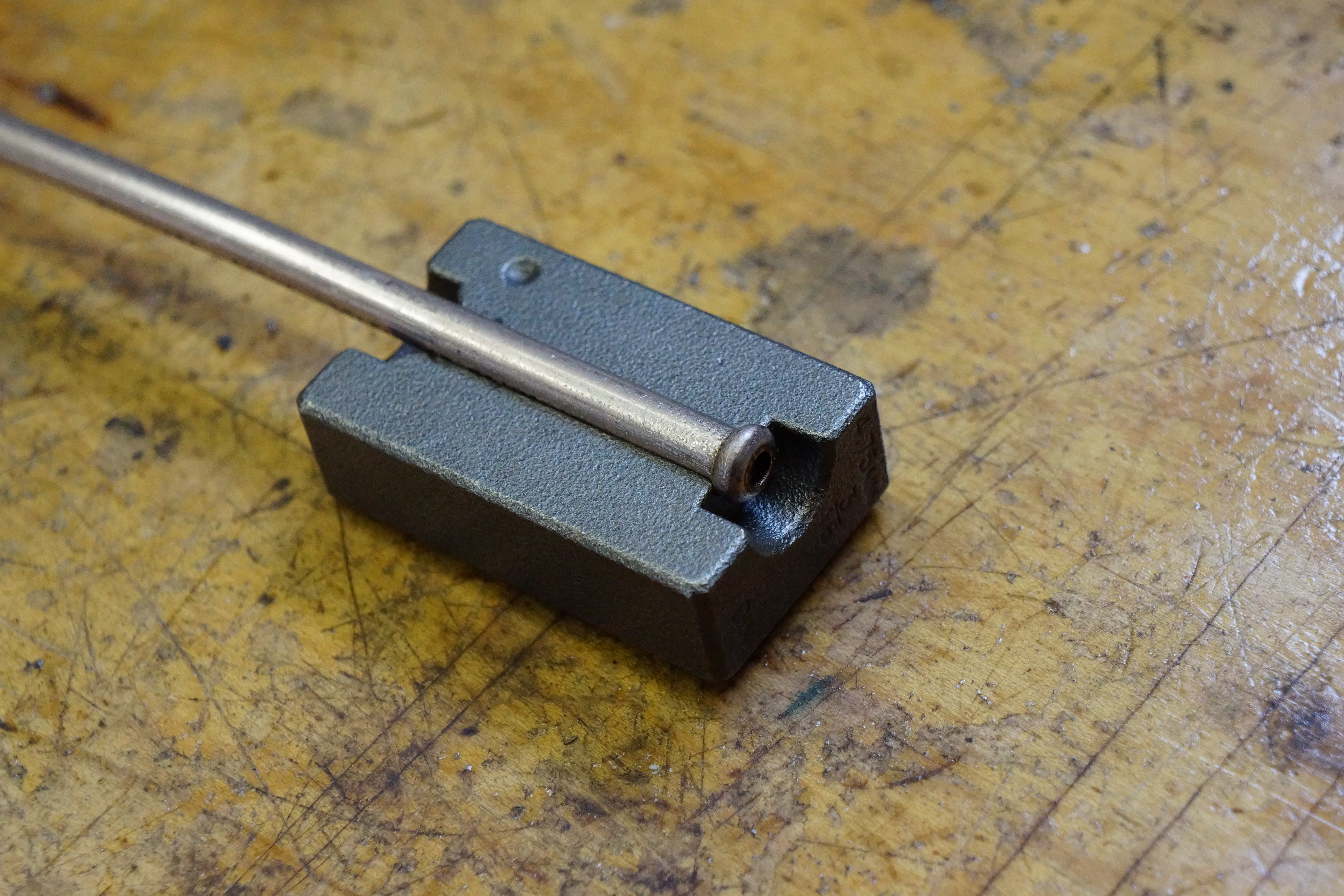
Clamping the brake line forming tool in the bench vise frees up both hands to manipulate the line
As of today: all 3/16” brake lines have been replaced with new lines cut and formed by me, all new flare fittings are on, and all lines are in place on the car (some final fitting still needs to be done). All three rubber brake hoses have been replaced with steel woven reinforced pieces (this is a case where originality is easily overridden by better quality).
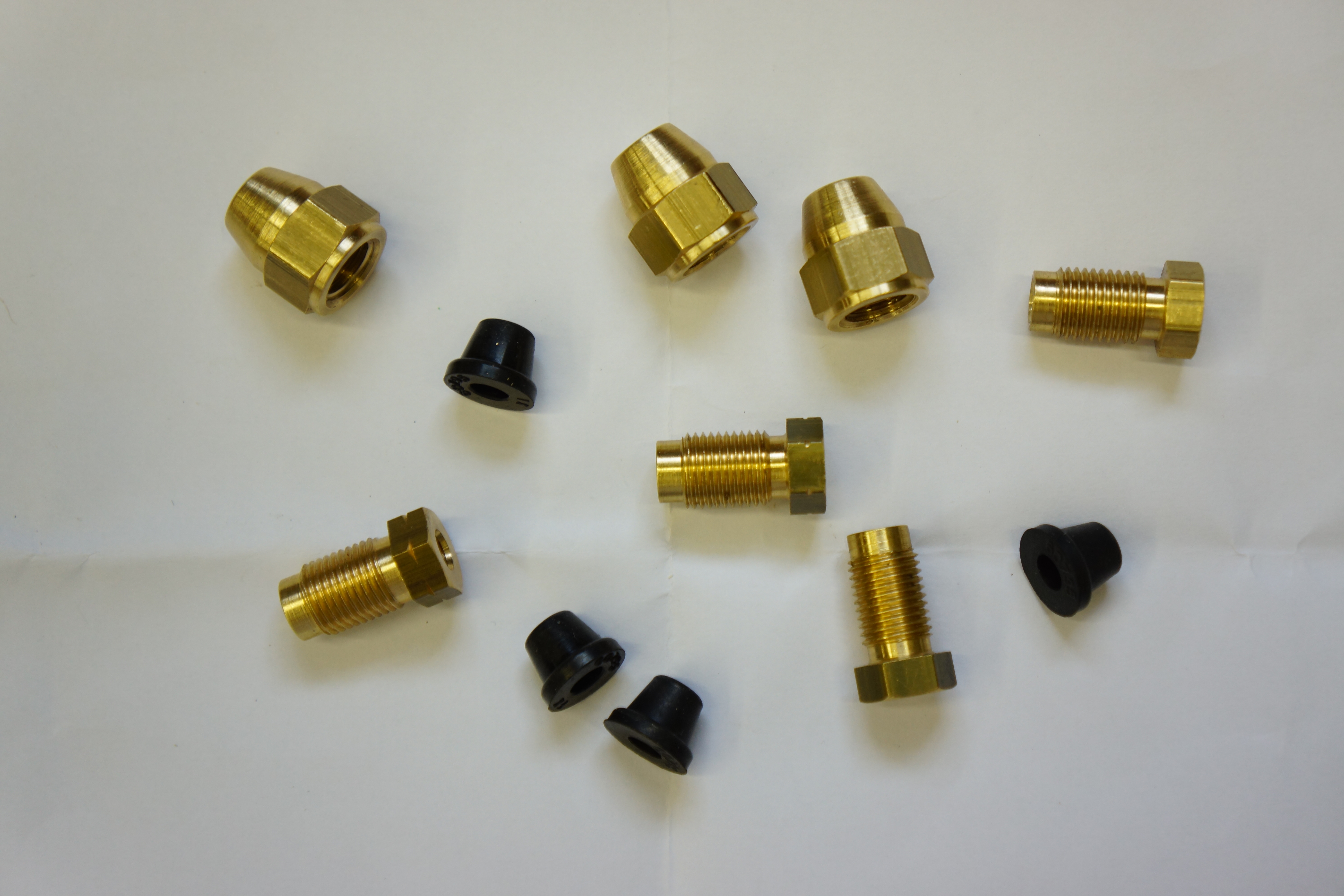
New male and female brake line fittings plus bleeder screw caps
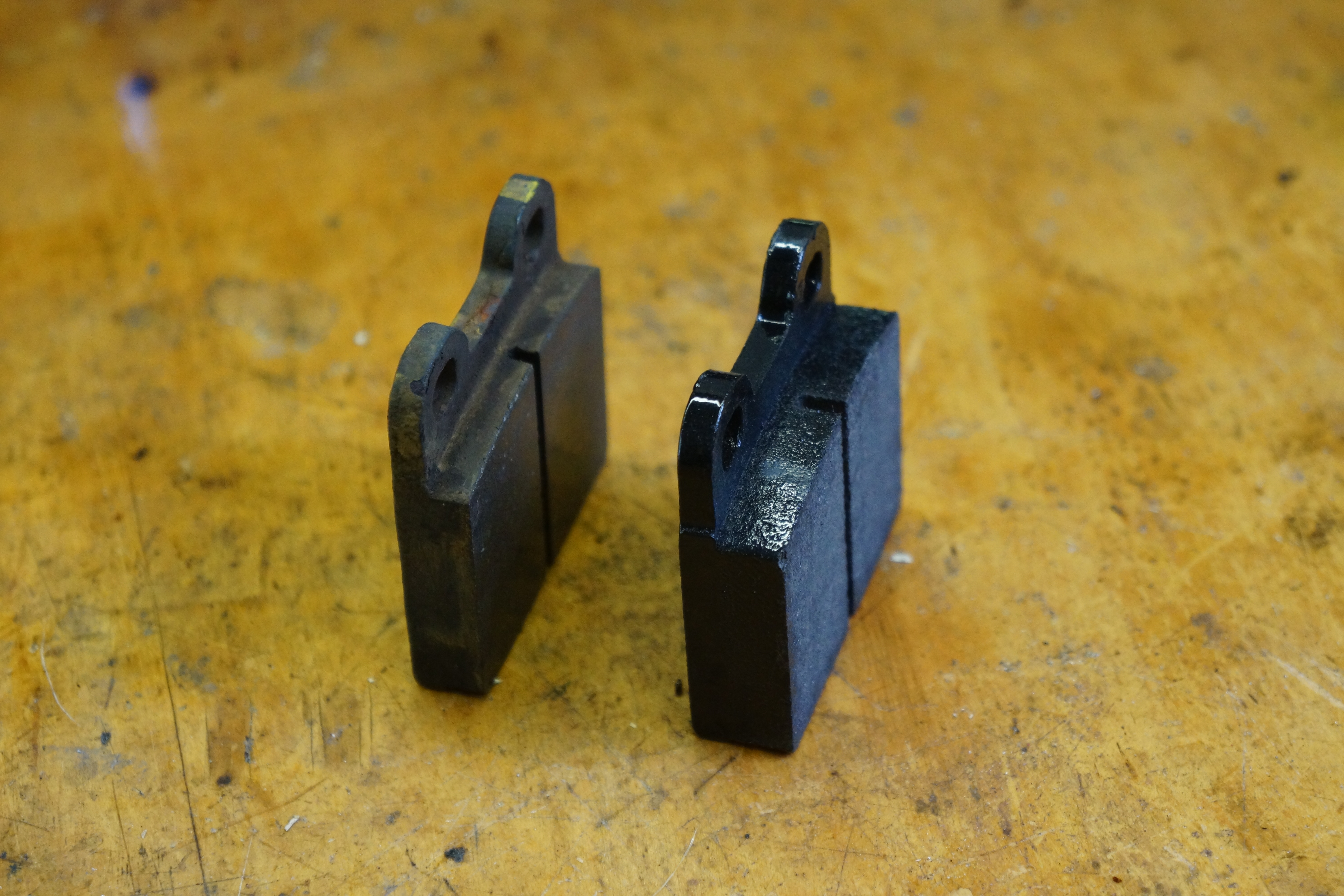
All four rebuilt brake calipers have been reinstalled, with new Ferodo pads in place (the Centric front pads I had installed several years back shed a lot of dust; let’s see if these are better).
Old and new pads side-by-side
The new master is (loosely) bolted in place, but the two brake line connections have yet to be made to it. (Not since the Isetta have I worked on a car with the master located below the floor. The Isetta was easy because the body had been removed from the chassis. The accessibility on the Alfa is horrible.) Once the lines to the master cylinder are done, I need to reinstall the pedal box in the driver’s footwell, as all three pedals had to be loosened/removed to gain access to the master.
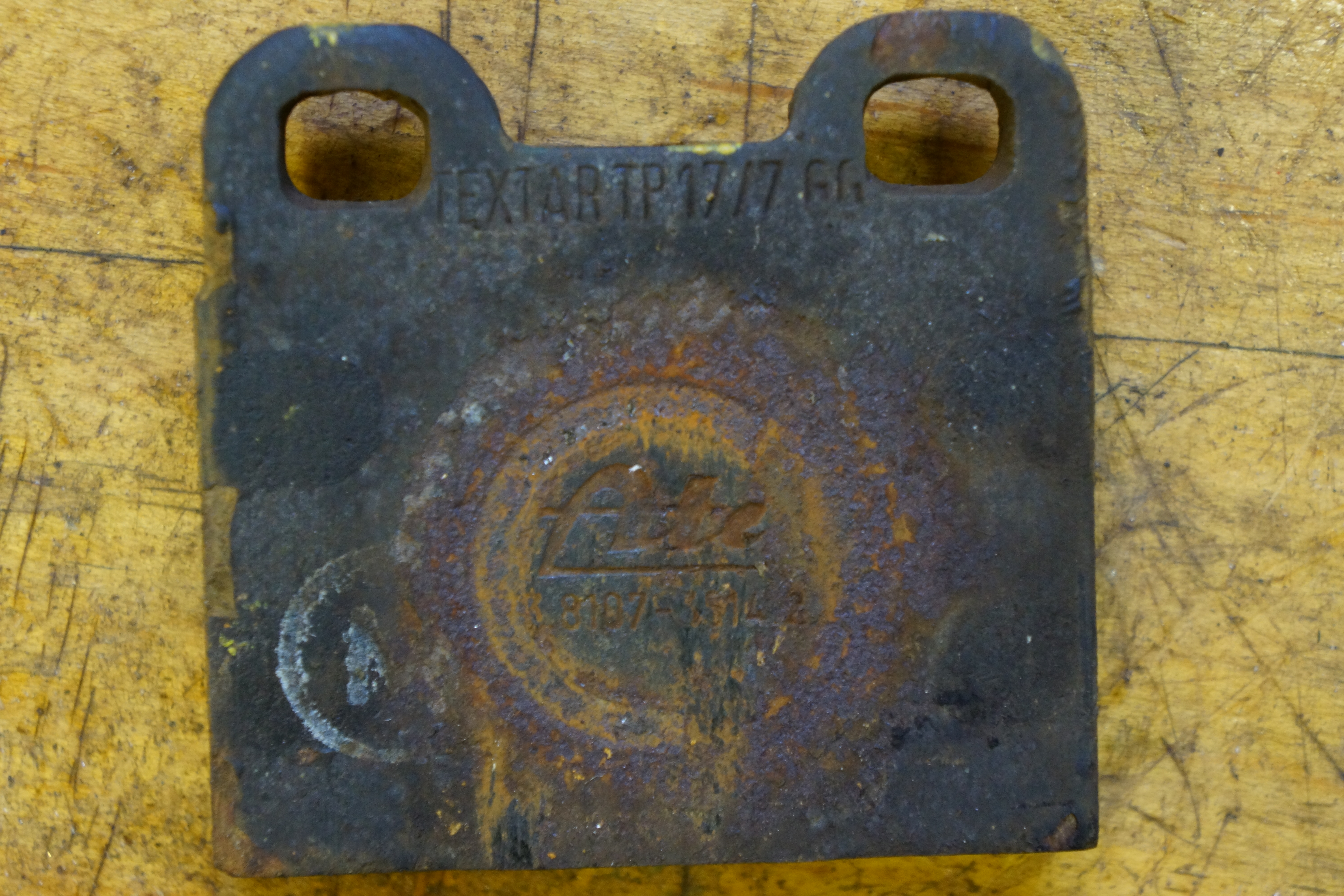
I can’t prove it, but “ATE” mark on rear pad might indicate it’s never been replaced
I then have the ‘extra’ job of replacing the positive cable for the battery. The previous owner had relocated this car’s battery from the engine compartment to the trunk, and used (in his own words) “a battery cable sourced from a junkyard Renault”. Since purchasing the car from him, he has recommended that I replace this cable. I’ve purchased a much heavier-duty one from Taylor Cable, which needs to be cut to size and have the appropriate terminals connected. Part of the intake plenum was removed for access to the starter, so that will need to go back together.
New caliper pins (L) didn’t fit, had to clean up & reuse old ones (C & R). Never throw old parts away!
The goal is to get this vehicle off the 4 jack stands upon which it’s been sitting before we reach the first anniversary of the brake seizure which happened in July 2019. I miss driving my Alfa! As I said, there is light at the end of the tunnel.
A big part of this brake project has always been the intention to replace all the hard lines. It was back in the fall of 2019 (days we’ll forever remember as “pre-coronavirus”) when I purchased a 25’ roll of new CuNiFer (copper/nickel/iron) brake line (from FedHill) and all new line fittings (from Classic Alfa), knowing that the day would come when I’d need them.
Well, that day did come, and I’ve spent a somewhat enjoyable last few days in the garage making up the new lines. The rear rotors and calipers have been bolted back in place, so with the old lines as templates, I cut the first two new lines for the two rear calipers to the appropriate lengths.
The creation of new brake lines requires that the ends be flared, which requires a special tool. I have one of those cheap old flaring yokes, a tool I’ve had for so long that I couldn’t tell you the last time I used it. Maybe never. My good friend Mike G owns a high-end brake flaring tool kit made by Eastwood, which he generously loaned to me. I’m going to walk you through the step-by-step process, which on an old Alfa like mine can be a bit tricky! You’ll see in a moment.
The Eastwood brake flaring tool
With the exception of the ¼” hard line from the brake fluid reservoir to the master cylinder, all the other hard lines on the car are 3/16”. That’s the easy part. The fittings, on the other hand, are a mixed bag. The car’s four-wheel ATE calipers use metric M10x1 threads, while most of the remaining connections, such as at both front and rear T-fittings, use UNF 3/8”-24 threads. Further, the M10 end requires an ISO bubble flare, and the 3/8” end takes a double 45° flare. Please don’t ask me why – I’ll just point to the car and say “that’s how the Italians did it!”
The Eastwood tool, which I used for the very first time this week, is a bit intimidating at first. The instructions in the box are ok, but I thought it would be wise to cut a few short pieces of pipe and make some test flares (I purchased about 7 feet more brake line than needed, because sooner or later I’ll make a mistake and need to redo a line).
L to R: new fitting, test pipe w/ISO bubble flare, old pipe w/same
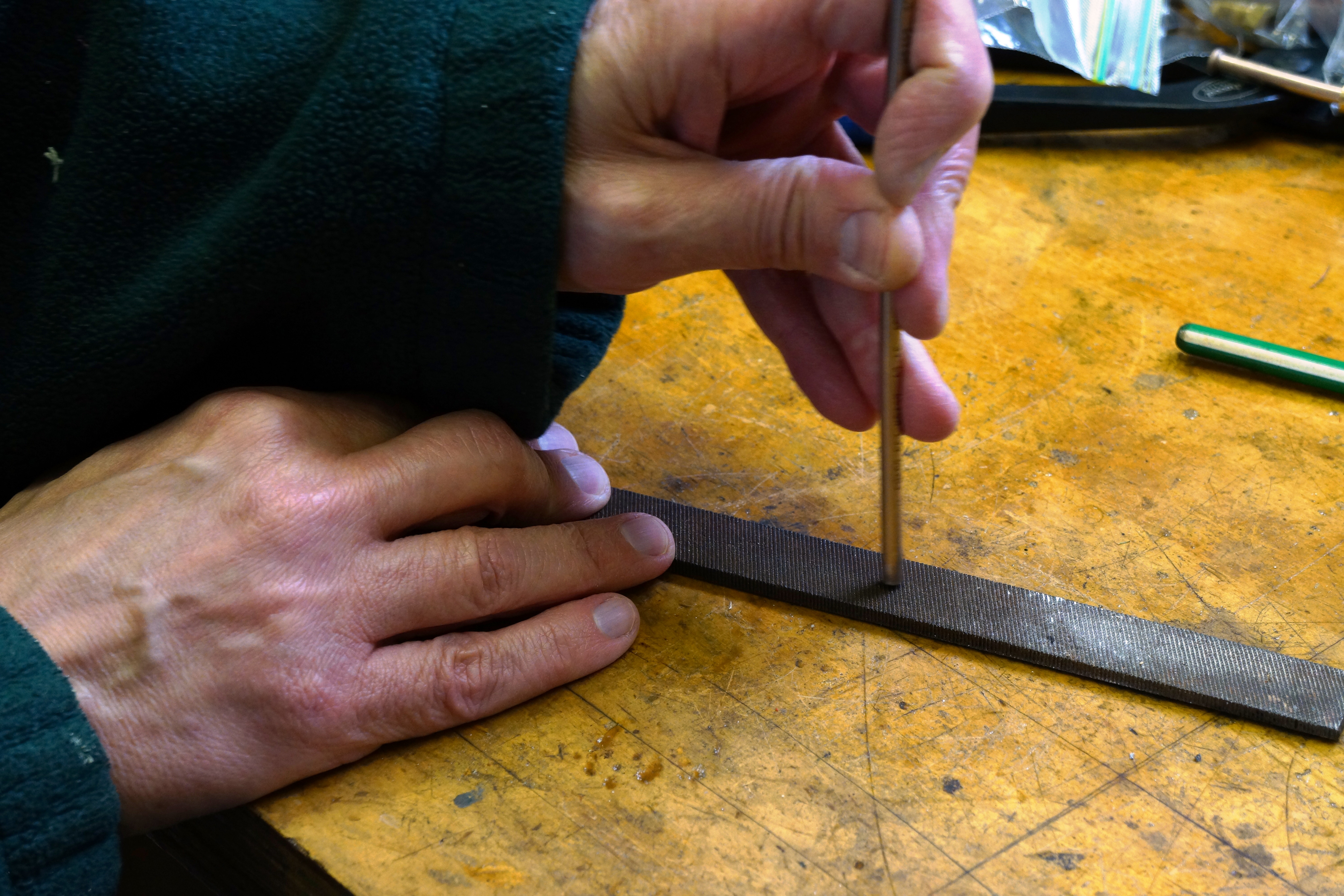
The Eastwood instruction book states that before you make a flare, you should do 3 things with the cut tube: run a file on the inside to remove burrs; run a file on the outside for the same reason; and slightly chamfer the edges. I dutifully followed instructions.
File the inside…
File the outside…
Chamfer the edges
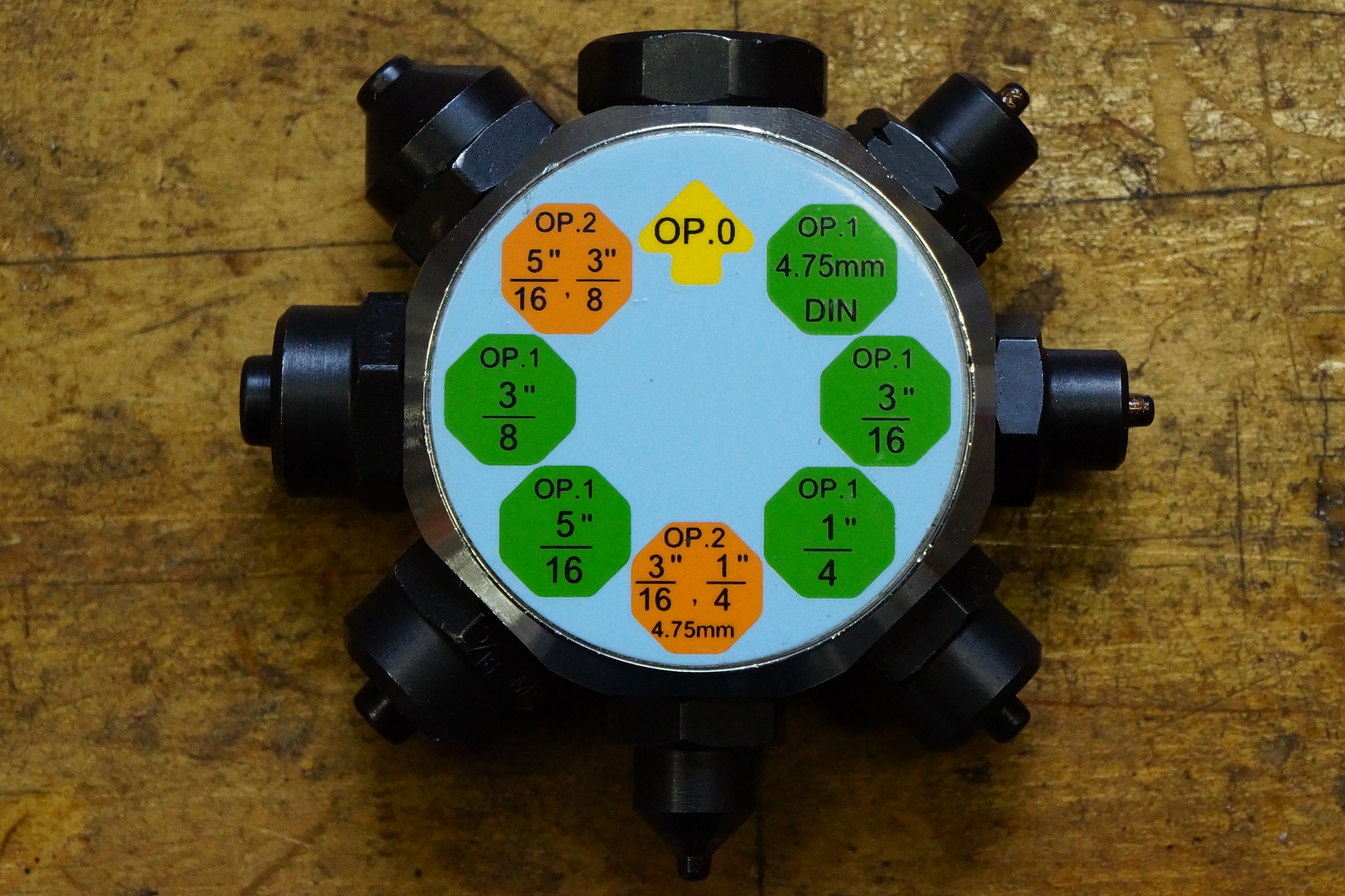
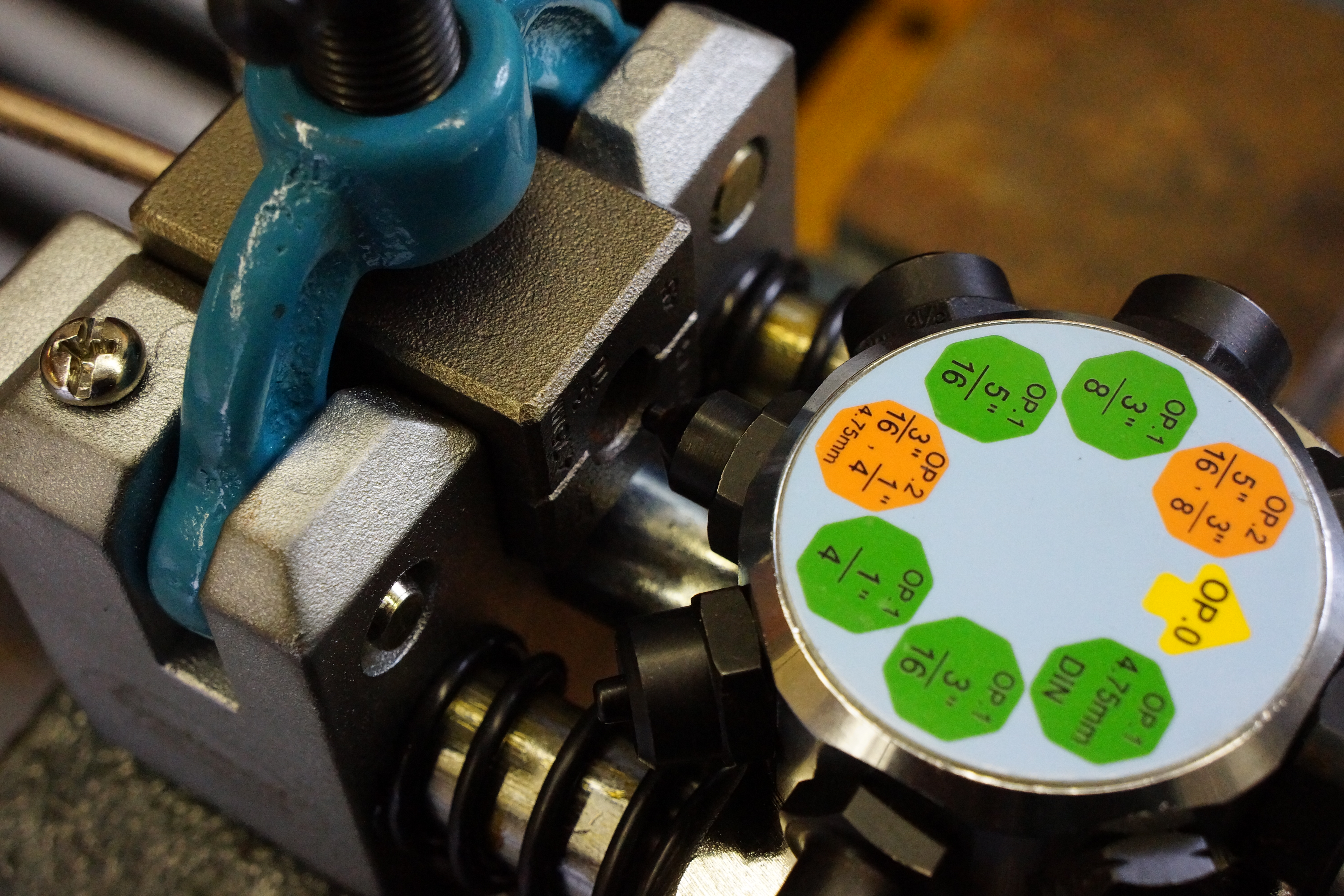
The tool itself is designed to be securely clamped into a bench vise. The two most important pieces which require your utmost intention are the tube-holding dies in 4 different sizes, and a rotatable disc with the various flare-forming dies. This is when I discovered that the 3/16” tube die is double-ended: it says 45° on one side, and DIN on the other. The instruction book didn’t say too much about this.
All the flare-forming dies are on this disc
3/16″ die, 45 degree end
same die, DIN end
I grabbed the 3/16” tube-holding die and placed it into the tool, with the 45° double-flare at the business end. The tube itself was inserted between the two halves of the die, and with the disc’s “OP. 0” (Operation Zero) facing the tube, I pulled the handle. This step simply squares up the end of the tube with the end of the die. Once done, I made sure the clamp was tight.
OP ZERO before squaring the tubingOP ZERO after tubing end is squared with die
Rotating the disc to “OP 1, 3/16”, I again pulled the handle. As a final step, the forming die disc was rotated to “OP 2, 3/16”, the handle was pulled, and I removed the tubing to examine my work. It looked good! I had a nice, neat 45° double flare.
OP 1, step one of the 45 degree flare
OP 2, step 2 of the 45 degree flare
45 degree double flare done!
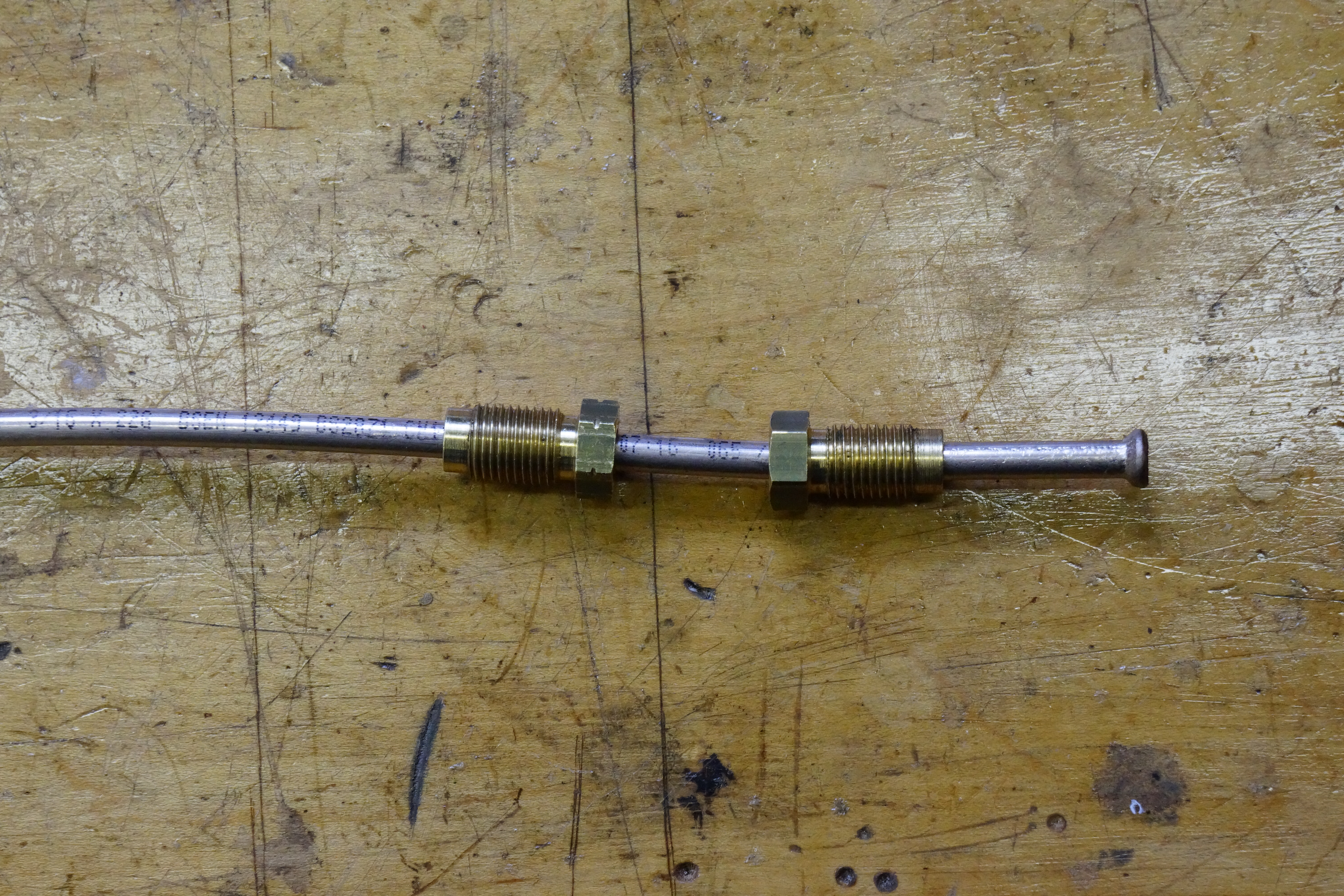
Before you flare the other end of the tube, you MUST slide on the two flare fittings; once both ends are flared, you’ll never get them on. In my case, not only did they need to face the correct way, they needed to be the correct threads! With the 45° double flare done, the 3/8” fitting went on first, and then the M10 fitting. It is highly recommended to delay the celebratory glass of vino until AFTER these steps are completed.
Pay attention! L to R: M10 flare fitting, 3/8″ flare fitting, 45 degree double flare on pipe end
It was a good thing that I had made some test pipes, which is when I discovered that the DIN end of the tubing die would make the needed ISO flare. I further discovered via experimentation that while the forming die does have an “OP 1” and “OP 2” for the DIN flare, I needed only “OP 1” to get a bubble flare that matched my old brake line.
ISO bubble flare done!
I’ve made two lines so far, and am quite pleased with the progress. It’s a nice feeling to have rounded the curve and to have begun reassembly. With most collector car events cancelled for the spring, the pressure is off, but the progress continues.
I’ve often referred to the two years I spent as a professional automotive technician as my “post-college” graduate work. It was a different kind of education, and included the benefit of earning a salary. One of the earliest lessons, and one I still carry today, is that there is no substitute for having the right tool for the job at hand. The correct tool ensures that the repair is done correctly, safely, and within a reasonable amount of time. It is not an exaggeration to state that there were times when sweat dripped from my brow, and curses sprang from my lips, when the lack of the appropriate tool made a repair attempt a real struggle.
A corollary lesson states that sometimes, one needs to practice some creativity and “invent” a tool, perhaps by assembling one from hardware parts, or by modifying an existing tool. This point was put into practice during the Isetta restoration, as tools for that car aren’t exactly found in your local NAPA store.
The challenge rose up again during the recent brake work on my Alfa. I found myself struggling with the reassembly of the parking brake shoes, which reside inside the rear brake rotor ‘hat’. The shoes and their assorted springs and clips came apart easily enough. But now my efforts to put it all back together were just taking too long.
Let me be more specific: the brake shoe assembly mounts to a backing plate, like on most cars. Unlike most cars, though, the wheel hub is mounted on a bearing that is press-fitted into place through the backing plate. The parking brake reassembly would be easier if the hub were not in the way, but to remove it, I would need to remove the entire axle and press the hub and backing plate apart. That was more work than I wanted to bother with. I was convinced that there was a way to put the parts back on with the hub in place.
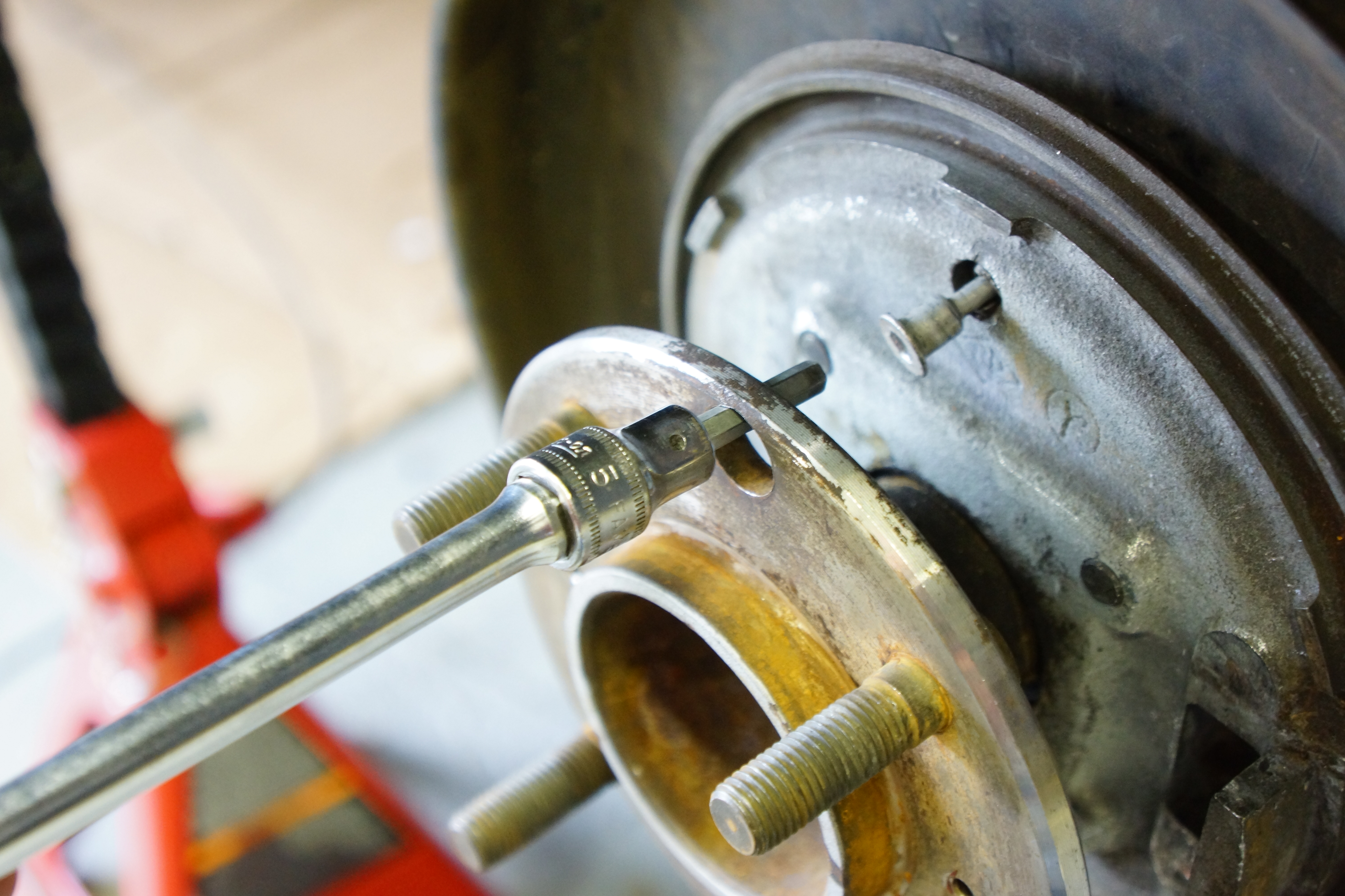
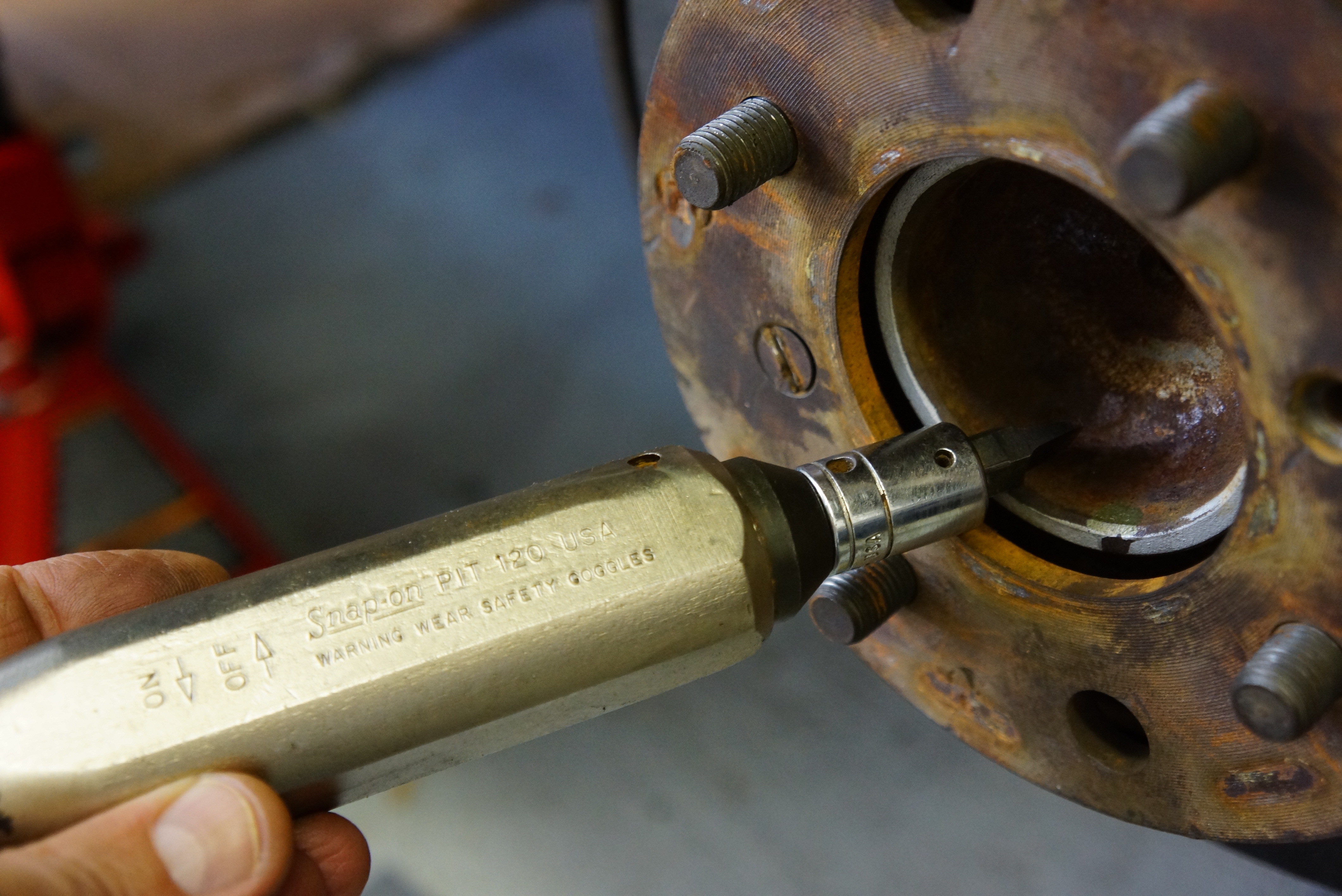
And Alfa Romeo actually made that accommodation. The hub surface has two additional holes, lined up in such a way to allow a tool to pass through them to access the brake shoe hold-down pins. The pins require a 5mm Allen tool, and I have one as a 3/8” drive socket. Since there is so much spring pressure to overcome, putting the Allen socket on an extension, with a 3/8” drive ratchet wrench, provides way more leverage than one could ever get from a tiny hex key.
Original 5mm hex socket on extension is placed through access hole in hub
Herewith was the problem: I could not push the pin in far enough to engage its lock, because the socket was too wide to pass completely through the hole in the hub. I briefly considered grinding down the socket, but a close examination revealed that would likely weaken it to the point of failure once an extension or a wrench was snapped into place. I briefly (like, for 10 seconds) considered enlarging the hole in the hub before rejecting that crazy idea. (Repair lesson #39.b.2: when making permanent modifications, always do so to inexpensive, replaceable objects, NOT to complex, difficult-to-replace components of the vehicle itself.)
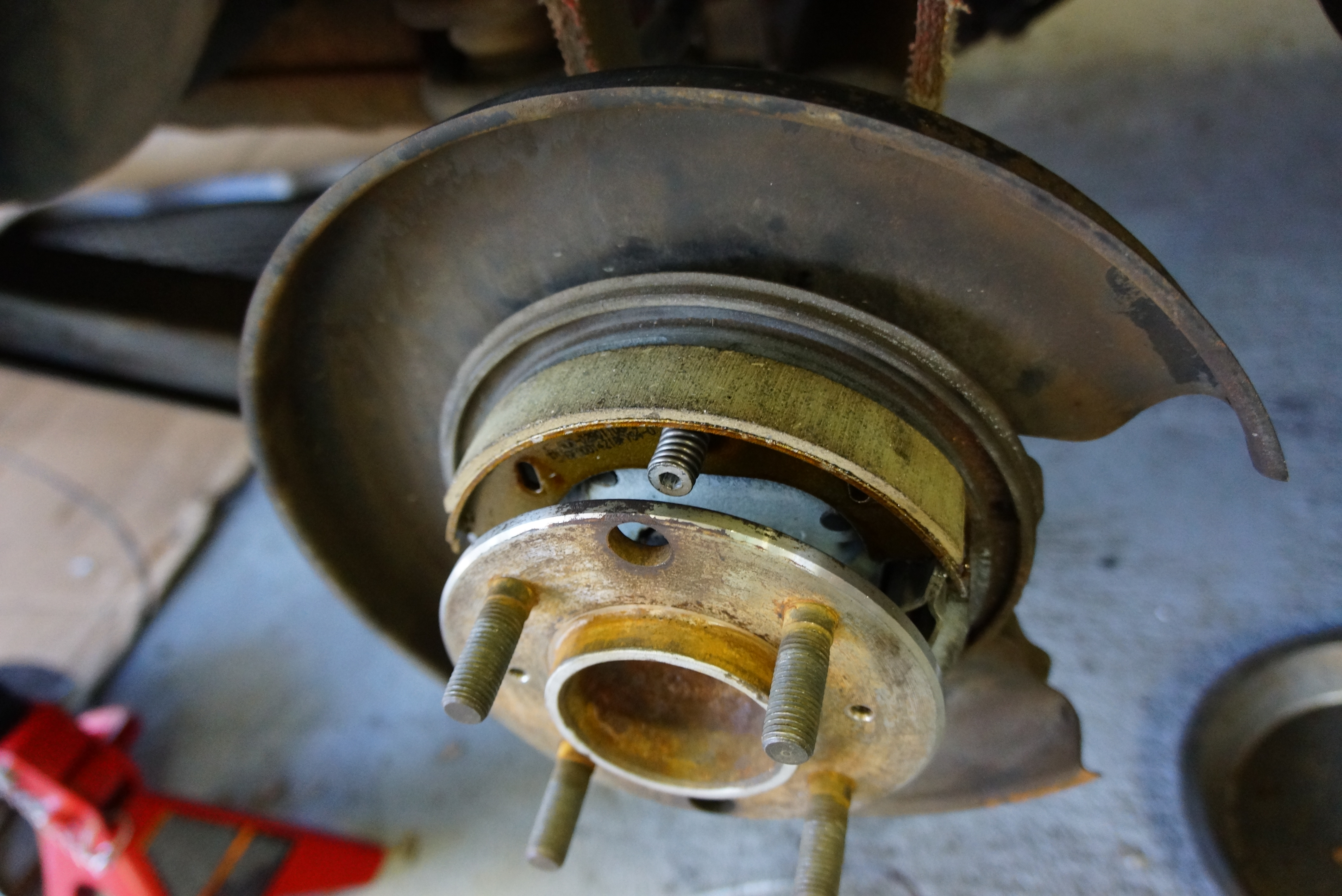
Socket bottoms out before pin can be fully inserted in backing plate (spring and shoes removed for clarity)
Staring at things for several minutes brought forth the revelation that if the 5mm hex shaft were longer, I’d have what I needed. After considering a Home Depot run, which I internally wagered would yield a 25% chance of success, I challenged myself to modify the tool I owned. Could I do this in less than an hour? I thought it entirely reasonable.
Here is the Snap-On 5mm Allen socket about to be modified
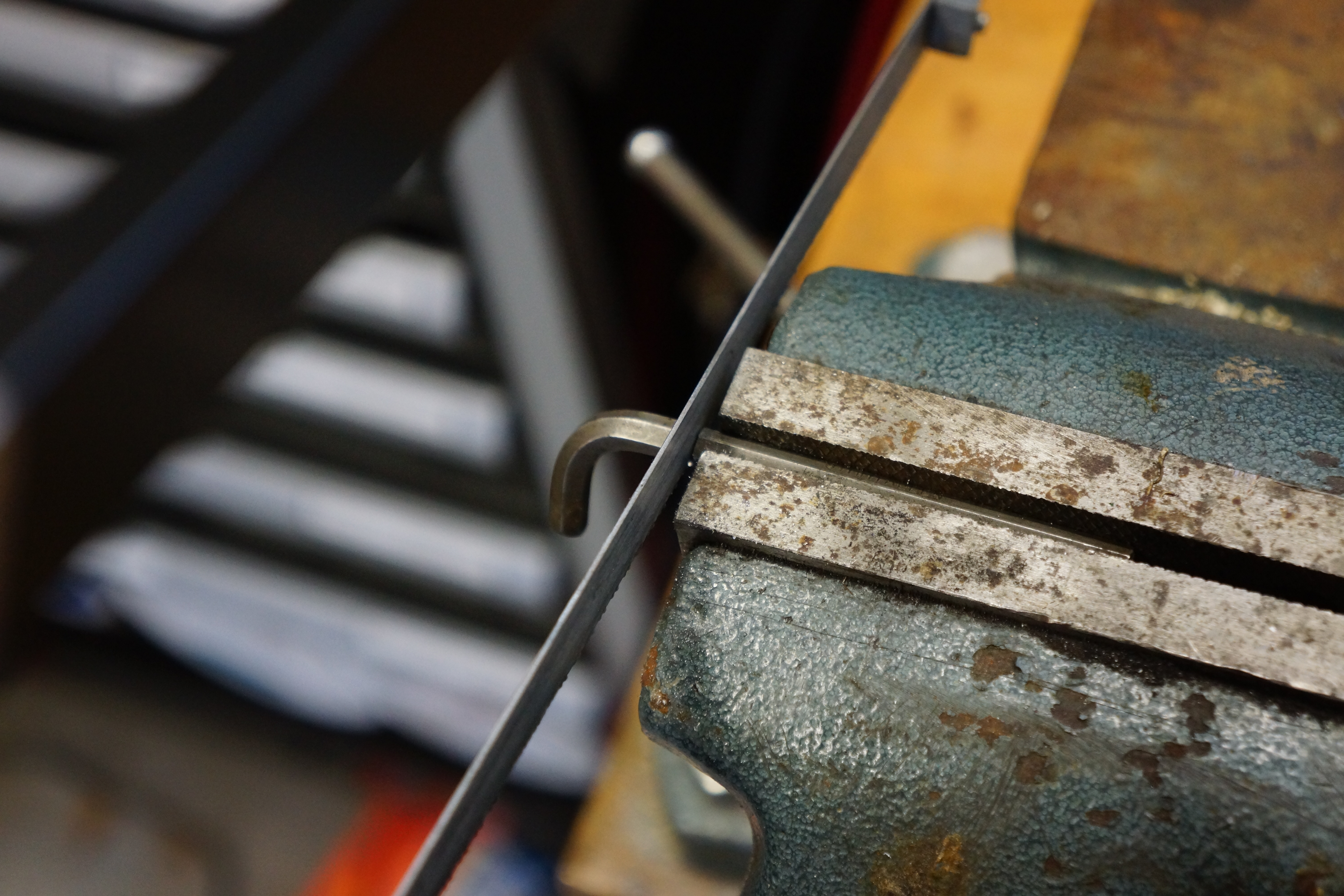
With a 3/32” drift, I hammered out the roll pin and pulled out the existing 5mm bit from the socket. I found a standard 5mm hex key in my Allen key collection, and tested it at the car. It was long enough for my purposes. Next, I secured the longer hex key in the bench vise and hacksawed off the short end. (I really should have pulled out the Dremel tool for this step, as the hardened steel took longer than I thought it would to hack off.) I filed the end smooth, and it fit right into the socket. My attempts to drill a hole in it to reinstall the roll pin resulted in two broken drill bits – like I said, that tool steel is hard! But the new bit was a tight fit in the socket, and since I’d be pushing against it, not pulling on it, I let it be, feeling certain that there was nothing to worry about.
Drift makes short work of roll pin removalThis hex key is about to give up its life for a greater goodHacksaw got the job done, but it took 10 minutes of muscular effort
Total time to modify the 5mm Allen socket: approximately 30 minutes. I attached my ‘new’ socket onto an extension, snapped on a ratchet wrench, and was easily able to engage the brake shoe pins in their locks. Mission accomplished!
“New” socket has considerably longer shaft
I’m keeping my new, longer 5mm Allen socket as is. Who knows when someone might need my help with their Alfa Romeo parking brake shoes? “Hey, I got just the tool for that!”
Success! Longer hex shaft makes short work of engaging pin
The weather today in downtown Neshanic Station NJ reached a balmy (for February) 55 degrees F. While I desperately do NOT want it to be 90 in April, I didn’t mind today’s spring preview; after all, the calendar claims we’re only four weeks away.
That high temp was accompanied by blue skies and lots of sunshine, all of which inspired me to get back to the garage. The Alfa’s brakes have been ignored since last autumn, and even I can’t believe how long it’s been since I’ve put up a blog post about my progress, of which there has been scant little. I have been ordering parts, reading service manuals, and perusing online forums, but there’s been no actual wrench-turning since before Halloween, which feels like a very long time ago.
Old (upper) and new (lower) parking brake cables- note boots
While today’s progress was not substantial, it was significant. The corner has been turned; everything that’s to be removed has been removed. I am now embarking on reassembly, using new parts as required. Starting at the left rear, a new parking brake cable was installed, and a new upper e-brake shoe was also put into place.
Parking brake shoes & springs: old (left) and new (right)
Projects never proceed at an orderly pace. There may be a flurry of activity, then a slowdown. Other, smaller projects may jump the line. Sometimes, it’s a parts delay that forces the pullback. However, there’s something to be said for picking up the tools again after a long layoff: it reinvigorates the soul, and reawakens the motivation.
LR upper e-brake shoe in place
I’m also motivated by an email I received from the NJ Chapter of the Alfa Romeo Owner’s Club, announcing a one-day spring tour for Sunday April 26. That’s nine weeks from today. I plan to drive this car on that tour. Sounds like I have lots of time, but we know how quickly that time will fly. The last time I drove my Alfa was July of last year. I have not gone this long without driving it since my purchase in 2013. So I’m motivated! Let’s hope the trend for an early spring continues.
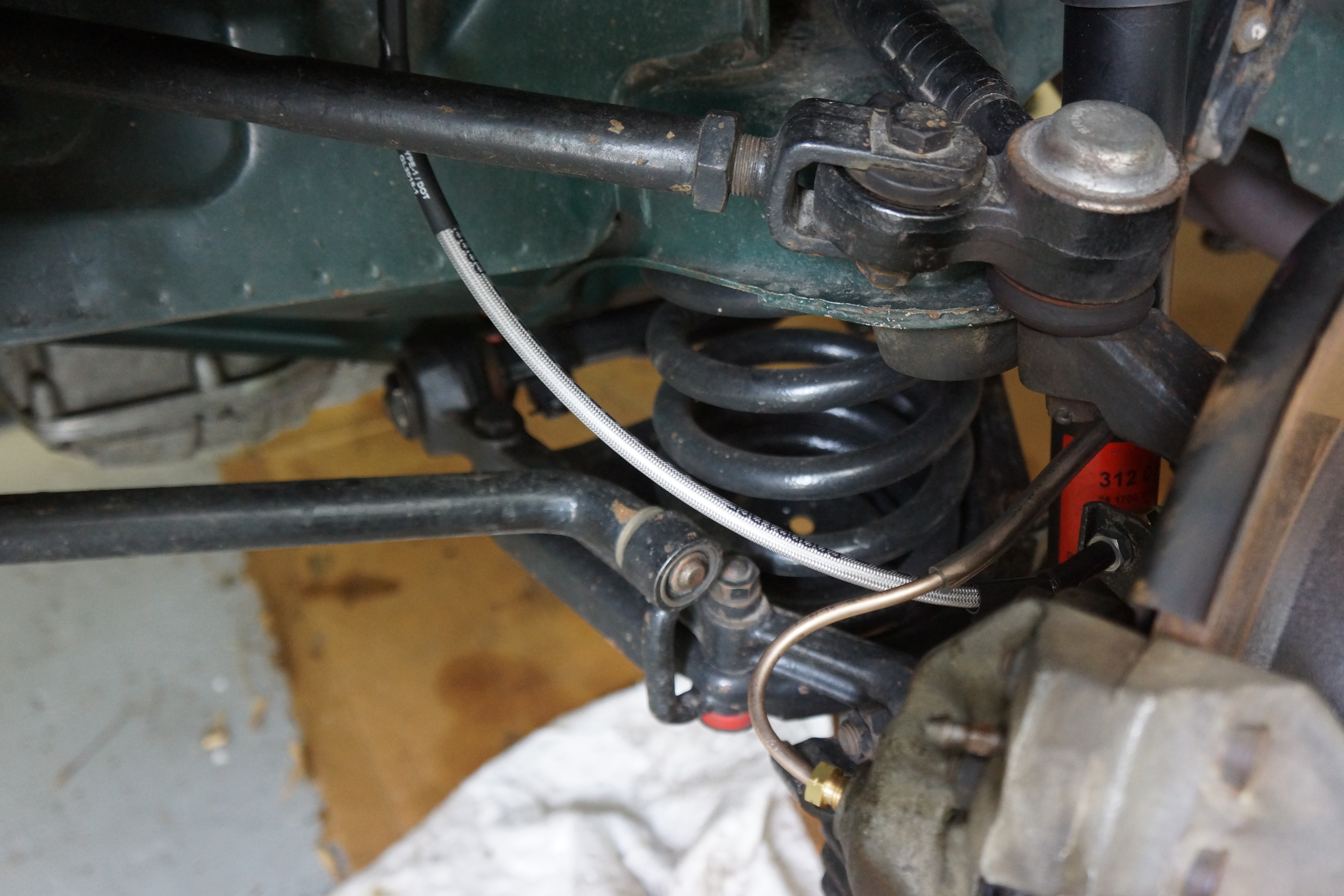
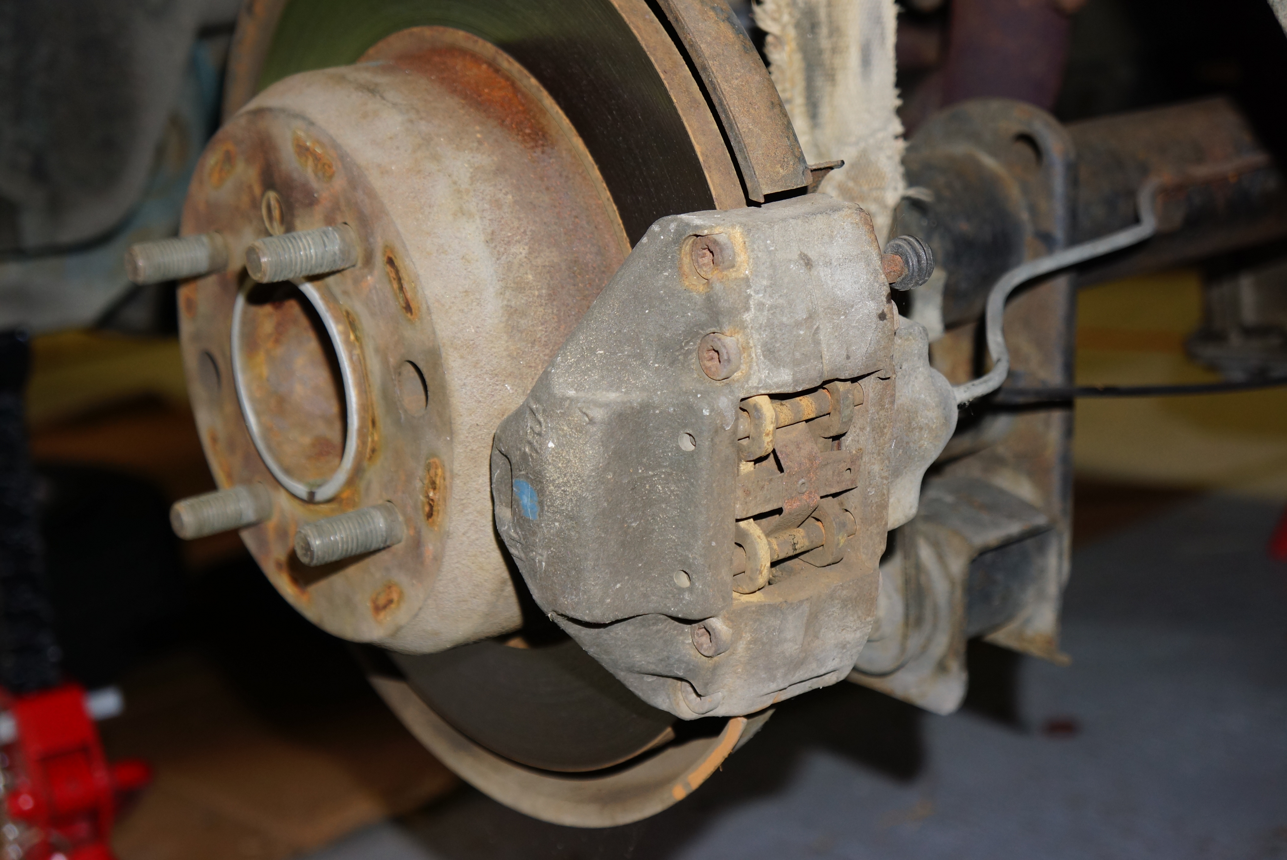
In Part 2, we covered the ongoing caliper overhaul, both front and rear. While waiting for the caliper rebuild parts to show up, I decided to remove the rear rotors and inspect the parking brake set-up.
Left rear disc, caliper, and brake line
Similar to what Volvo has used for decades, the rear rotors sit over a set of drum brake shoes which apply to the inside of the rear disc “hat”. On the Alfa, these are cable-operated. It was always gratifying that my car’s hand brake worked, but it required a significant tug of the handle to engage.
First challenge was removing the two slotted-head screws holding each rear rotor to the hub. An ordinary screwdriver wasn’t getting the job done, so I resorted to one of my favorite tools: my Snap-On hammer-driven impact driver. A long time ago, Andy Finnegan, the shop foreman at the first Volvo dealer that employed me, suggested this tool to me. While I infrequently use it, it’s one of those tools that makes you glad you have it for the occasions you really need it. This was one of those occasions.
The right tool at the right time can save hours of time and frustration – note slotted screw in rotor face
A few taps with a hammer, and the screws were loose (I also bought new replacements on the chance that I would mangle the heads during removal.). But getting the disc off also required a few heavier hammer blows. Eventually, the rotors were off, first on the driver’s side, then the passenger side.
It would not surprise me if I were the first person to expose the parking brake shoes since this car left Italy. Remember that when I bought it, the car has 54,000 original miles. I also have reason to suspect that the rear brake pads were original to the car. There has likely been little need to check or service these components.
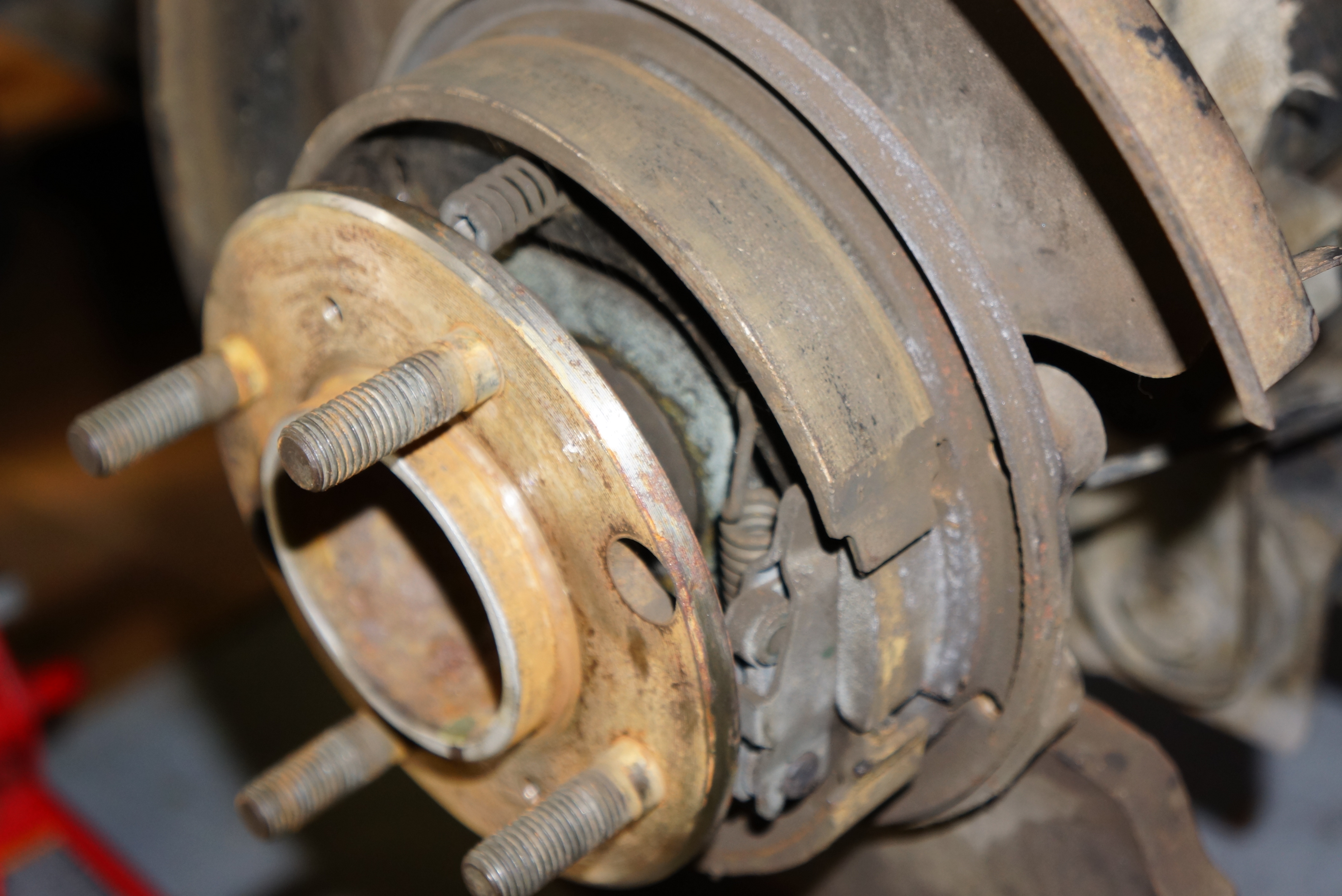
Note star wheel on left
and cable linkage on right
With some effort, I removed the brake shoes on the driver’s side (access is conveniently limited by the hub). The arrangement is typical, with a star wheel for adjustment, and two springs holding the upper and lower shoes. A cable extends from the differential through an access hole in the backing plate, pulling a lever which spreads the shoes. After taking the one side apart, I decided to leave the passenger side intact for reference, and ordered all new parts from Classic Alfa.
Old shoes and springs will be replaced
It was also time to remove the master cylinder. With its so-called “standing pedals” hinged through the floor, my ’67 is one of the last Giulia coupes so configured. Within a year or so (varying by model), Alfa would switch to “hanging pedals” and mount the master cylinder in the conventional location on the firewall.
Standing pedals – accel pedal has been removed
I desperately searched for guidance on the Alfa forums for “master cylinder removal”, but nothing I came across addressed the underfloor location. So I tackled it on my own, and really struggled with it. There are two bolts which pass horizontally through the master cylinder, and these bolts mount into a plate that also holds the clutch linkage. Said plate didn’t look removable to me – that’s from the vantage point of lying on my back, with my nose about 3 inches from the car’s underside. Without removing the plate, there wasn’t enough clearance to remove the bolts. Through sheer luck, I wiggled the cylinder and the bolts and got the master cylinder cleared. But I’ll need to investigate this plate when it comes time for reinstallation.
View of master cylinder while on my back
There was also the matter of the two brake lines, both of which thread into the top of the cylinder. There was little choice but to loosen and drop the cylinder to give me access to the line fittings, but then I lost the leverage one gets from a master cylinder firmly bolted to something.
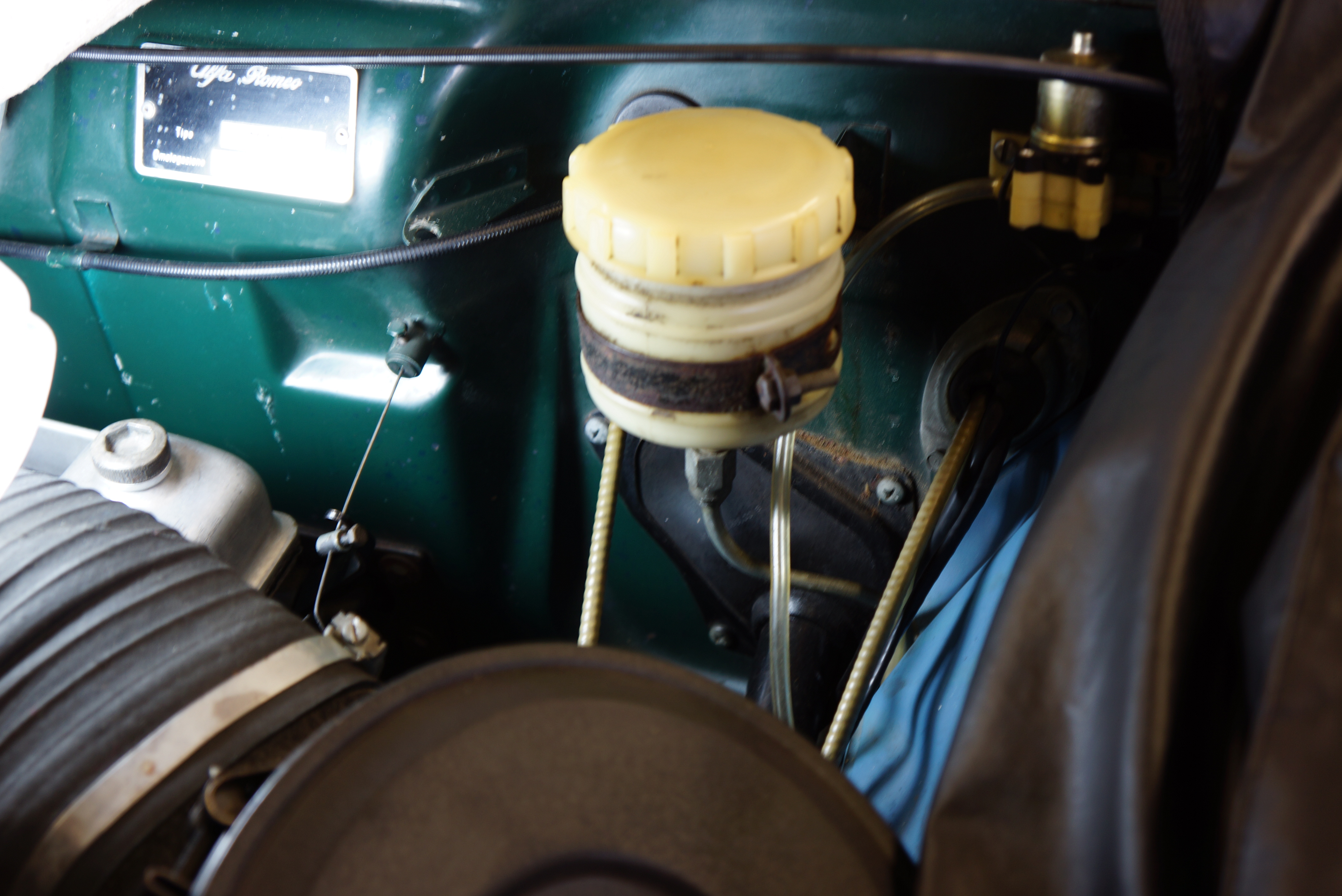
Brake fluid reservoir on firewall is where you’d expect to find m/c – note hard line which feeds it
Using my flare nut wrenches, the first fitting came out easily. The second one did not. I resorted to using a cheater bar (a length of pipe) on the wrench, and for the first time during this brake overhaul, the wrench slipped on the fitting and rounded it off. The fitting was seized. I cut the line with a pair of diagonal cutters, and the master cylinder was on my workbench. In a bit of good news, the fitting did come loose once I dropped a deep 6-point socket on it.
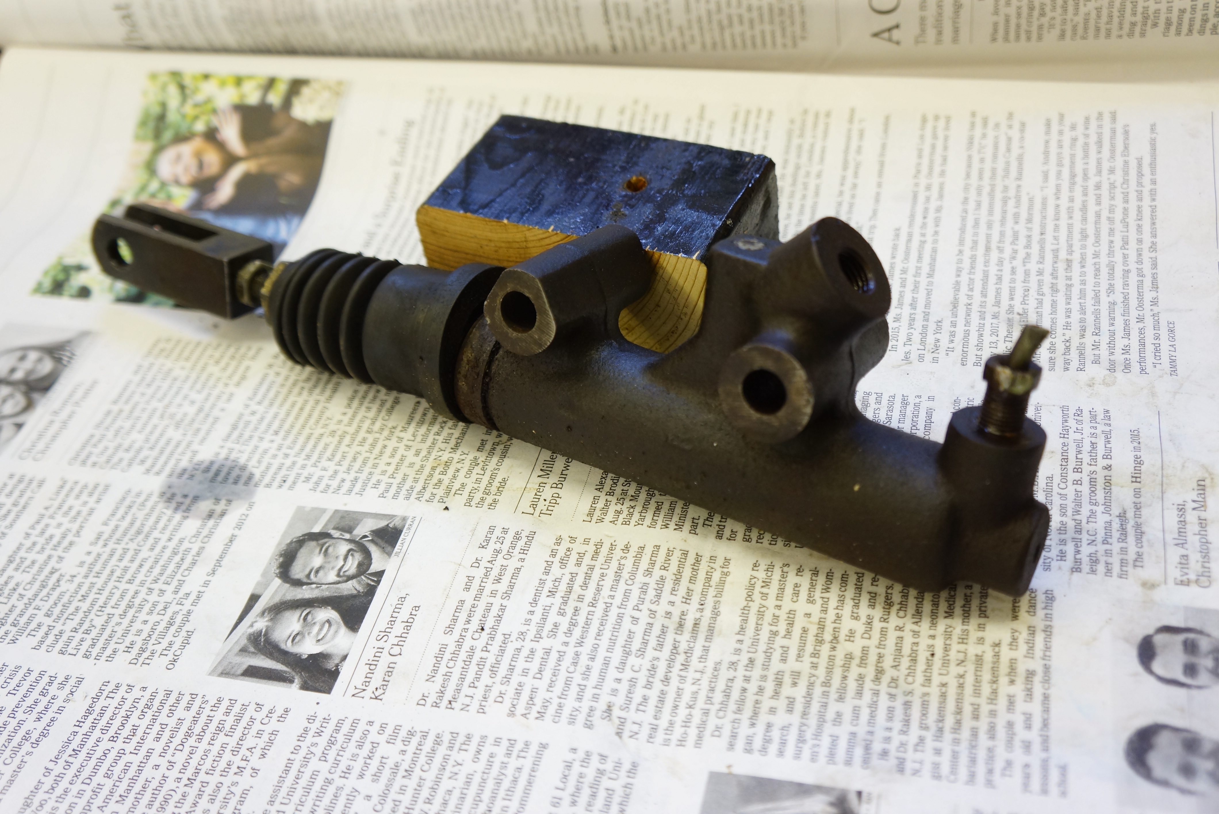
Master cylinder – note severed line and fitting in right-most hole
There is plenty to do next: finish the rebuilding of the two rear calipers, renew the parking brake parts, and rebuild the master cylinder. Parts were duly ordered and are on their way.